Thin Wall Machining Deflection: Cantilever Beam Model
Fundamentals of Thin Wall Machining Deflection: Mechanical Definition and Core Drivers
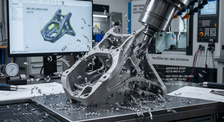
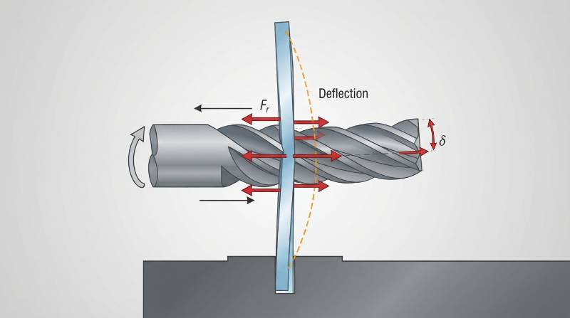
Thin-wall machining deflection occurs when cutting force vectors exceed the structural stiffness of an unsupported workpiece rib during milling. The interaction between radial tool pressure and workpiece compliance pushes the flexible wall away from the cutting tool edge, leading to geometric errors such as dimensional taper, wall thickness variation, and regenerative chatter.
Workpiece compliance is the inverse of structural stiffness (k⁻¹ = δ / F), representing the elastic displacement (δ) of an unsupported rib under normal cutting forces. Deflection severity escalates non-linearly when the feature height-to-thickness aspect ratio exceeds 10:1.
In high-speed milling, radial cutting forces generate an instantaneous repulsive vector perpendicular to the toolpath. When producing deep cavities in aerospace enclosures or RF shield cavities, these forces push the rib outward, leaving uncut stock at the top and excessive material removal at the root.
Material elastic modulus (Young’s modulus, E) sets the baseline deflection vulnerability across aerospace alloys. Aluminum 6061-T6 (E ≈ 68.9 GPa) and Al 7075-T6 (E ≈ 71.7 GPa) exhibit significant elastic displacement compared to Ti-6Al-4V (E ≈ 113.8 GPa) or 316L stainless steel (E ≈ 193 GPa). However, the lower specific cutting resistance of aluminum partially balances this disparity.
Overcoming these dynamic deflection mechanics requires production-grade equipment and rigid setups, standard within precision CNC milling services designed for critical structural components.
Analytical Modeling: Deriving Cantilever Beam Deflection for Thin Walls
To predict wall behavior during peripheral milling, structural engineers model the vertical rib as a prismatic cantilever beam fixed at the component floor and free at the upper boundary. Classical Euler-Bernoulli beam theory governs the maximum elastic displacement at the beam tip.
δ_max: Maximum tip deflection (mm) | F_radial: Normal cutting force vector (N) | H: Rib height (mm) | E: Elastic modulus (MPa) | I: Second moment of area (mm⁴)
The second moment of area (I) defines geometric resistance against bending. For a rectangular rib cross-section of length L_w along the cutter feed path and wall thickness t, the moment of inertia relative to the bending axis is:
L_w: Effective engaged wall length (mm) | t: Wall thickness (mm)
Substituting the area moment into the beam deflection equation reveals that elastic deflection is inversely proportional to the cube of the wall thickness (t³) and directly proportional to the cube of the rib height (H³). Reducing wall thickness by 50% reduces bending stiffness by a factor of eight, compounding machining deflection challenges.
Cutting force decomposition divides the resultant machining force into tangential (Ft), radial (Fr), and axial (Fa) components. According to the Kienzle specific cutting force formulation, radial force (Fr) pushes directly against the wall face:
kr: Radial force ratio | kc1.1: Specific cutting force coefficient (N/mm²) | b: Axial depth of cut ap (mm) | h_chip: Undeformed chip thickness (mm) | mc: Material correction factor
When the tool cuts along the rib, Fr induces a continuous line load. Because the rib flexes away, the actual radial depth of cut (ae) decreases dynamically, leaving residual stock and introducing a measurable taper from the base to the crest of the part.
The Deflection Evaluation Framework: Cantilever Mechanics vs. Dynamic Milling Realities
Pure 1D cantilever models provide an initial baseline, but real-world milling dynamics require a more comprehensive evaluation framework. In solid-cavity milling, thin walls are rarely free along their vertical edges; they connect to side ribs, corner fillets, or peripheral frames.
A 1D beam assumption assumes uniform boundary conditions across the cut, failing to predict structural stiffening at closed pockets. The real-world component functions as a 2D plate clamped on three edges and free at the top (C-C-C-F) or clamped on two edges (C-C-F-F).
| Mechanical Parameter | Classical 1D Cantilever Model | Clamped-Free 2D Plate Boundary Mechanics |
|---|---|---|
| Deflection Formula | δ = (Fr × H³) / (3 × E × I) | D × ∇⁴w = p(x,y) (Biharmonic Plate Equation) |
| Corner Stiffening Effect | Ignored (Assumes constant compliance along length) | Accurately modeled (Compliance drops to zero at corners) |
| Taper Prediction Accuracy | Linear to parabolic across depth only | Saddle-shaped deflection profile along length and depth |
| Tool Engagement Response | Static normal load vector | Dynamic modal interaction with varying phase shifts |
To bridge the gap between static mechanical theory and multi-axis milling, Tyneen utilizes an integrated dynamic compliance framework that maps tool helix angles, feed per tooth (fz), and empirical specific cutting force coefficients (kc).
The Tyneen Dynamic Compliance Matrix (TDCM)
The TDCM evaluates rib stability prior to code generation by cross-referencing three core process parameters:
- Modal Wall Receptance: Dynamic stiffness frequency response functions (FRF) measured across the unsupported rib profile.
- Helix Angle Force Redirection: Selecting cutter helix angles (e.g., 38° to 45°) that convert radial repulsive forces into axial loads directed toward the machine base.
- Chip Load Thresholds: Maintaining an undeformed chip thickness above the tool cutting edge radius (hn > r_edge) to avoid material burnishing and excessive normal force buildup.
Advanced CAM Strategies: Suppressing Deflection Through Kinematics and Toolpaths
Traditional unidirectional profile passes often scrap thin-walled parts. As the tool traverses an unbacked rib, bending increases toward the center span. Applying advanced CAM strategies controls dynamic force vectors, balancing the process to achieve strict dimensional accuracy.
Waterline Stepdown vs. Trochoidal Peeling
Traditional roughing cuts the entire wall height in wide axial passes. In contrast, waterline peeling alternates stock removal down the rib in small axial steps (ap = 0.5 to 1.5 × tool diameter) paired with shallow radial engagements (ae = 0.05 to 0.1 × tool diameter).
High-efficiency trochoidal toolpaths maintain a constant tool engagement angle (θ_eng ≤ 35°), preventing the sharp radial force spikes typical of standard corner passes. This constant engagement keeps cutting forces steady, preventing wall chatter.
Climb Milling vs. Conventional Force Vectors
Climb milling starts with maximum chip thickness and reduces to zero at exit. This directs cutting forces inward toward the bulk stock rather than pulling outward on the flexible rib.
Conventional milling begins with a rubbing phase that generates elevated normal forces before the shear zone forms. This rubs the rib face, inducing deflection and causing chatter marks. Climb milling remains essential for thin-wall finishing.
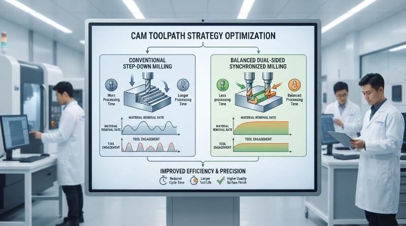
Balanced Dual-Sided Synchronized Milling
On complex 5-axis platforms, synchronized dual-spindle or opposed toolpath kinematics balance deflection forces. By positioning opposing cutters across the rib, the radial force (+Fr) of Tool A matches the equal and opposite radial force (-Fr) of Tool B.
This dynamic force cancellation keeps net bending deflection near zero (δ_net ≈ 0), preserving wall verticality on ultra-thin webs without requiring structural support media.
Cutting Tool Selection and Dynamic Vibration Suppression
Standard square-profile end mills generate harmonic resonance on flexible webs. Tool geometry must be carefully optimized to dampen vibration and lower radial cutting forces.
Tool manufacturers suppress chatter using variable helix angles (e.g., 35°/38°) paired with differential flute pitch spacing (e.g., 88°/92°/89°/91°). Unequal spacing alters chip impact timing, breaking regenerative chatter cycles that disrupt thin-wall finishes.
Substrate stiffness is equally critical. High-modulus sub-micron tungsten carbide substrates (E_tool ≥ 600 GPa) minimize tool deflection, ensuring overall compliance is governed solely by workpiece geometry.
Using short tool overhangs (length-to-diameter ratio L/D ≤ 3:1) preserves system rigidity. Tool deflection follows the same cubic length relationship:
Reducing L_overhang from 5D to 3D yields a 4.6× increase in cutting tool structural stiffness.
Sharp cutting edges with hone radii under 5 μm and positive rake angles (+8° to +12°) lower primary shear stress. This geometry minimizes cutting resistance, enabling high precision across advanced 5-axis machining solutions.
Non-Mechanical Workholding and In-Process Stabilization Techniques
When rib geometries exceed extreme aspect ratios (height-to-thickness > 30:1), toolpath kinematics and tool geometries alone may not fully prevent deflection. In these scenarios, sacrificial support media provide physical backing during finishing passes.
- Low-Melting-Point Alloys (LMPA): Bismuth-based alloys (such as Cerrolow or Cerrobend) melt below 70°C, expanding slightly upon solidification. Pouring LMPA into pre-roughed pockets supports the rib like a solid block during final cuts, and can be melted away afterward without heat-treating the substrate.
- Water-Soluble Thermoplastic Polymers: Environmental and aerospace standards often restrict heavy metals. Water-soluble rigid resins provide comparable mechanical support (compressive strength > 45 MPa). These wash away cleanly in warm water baths (50°C to 60°C) with zero chemical residue.
- Phase-Change Waxes and Cryogenic Clamping: Hydrocarbon phase-change waxes secure fragile, open-profile parts. Alternatively, cryogenic chucks freeze thin features in chilled fluid beds during micro-milling, preventing tool deflection on deep ribs.
The 20:1 Aspect Ratio Micro-Milling Benchmark: Eliminating Rib Deflection in Aerospace Housings
Machining deep, lightweight cavities in radar housings and satellite avionics chassis presents significant manufacturing challenges. A critical benchmark involves finishing an Al 7075-T6 RF housing containing vertical isolation ribs with a 0.35 mm thickness and an 8.0 mm free height (a 22.8:1 aspect ratio).
Design specifications required perpendicularity within 0.008 mm, wall thickness tolerances of ±0.005 mm, and a surface roughness of Ra 0.4 μm, all without using sacrificial potting compounds that risk chemical entrapment.
 rib
Tyneen achieved this benchmark using synchronized multi-pass strategies on premium engineering alloys and aerospace materials. The production parameters included:
- Kinematic Machine Platform: DMG MORI NMV 5000 DCG 5-axis center with direct-drive rotary tables and thermal displacement compensation on the linear scales.
- Tooling Selection: Custom 3-flute ⌀3.0 mm ultra-fine grain carbide end mills with an unequal helix (38°/41°), 3 μm edge hone, and polished DLC (diamond-like carbon) coatings to prevent aluminum adhesion.
- Cutting Parameters: Spindle speed 24,000 RPM (cutting velocity Vc ≈ 226 m/min), chip load fz = 0.008 mm/tooth, step-down ap = 0.25 mm, radial step-over ae = 0.025 mm.
- Kinematic Toolpath Strategy: Stepped, alternating waterline clearing that removed material symmetrically on opposing rib sides, leaving a rigid support core behind the cutter at each depth level.
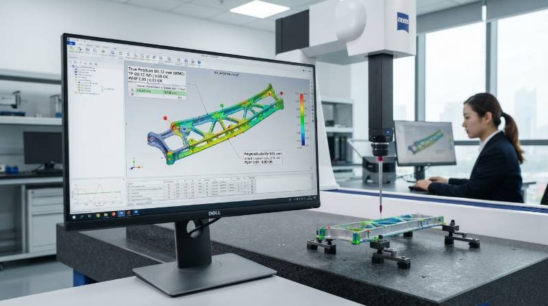
Full dimensional inspection on a Zeiss Prismo CMM confirmed wall thickness was held within 0.350 mm ±0.003 mm, vertical perpendicularity was maintained at 0.006 mm, and surface finish measured Ra 0.32 μm—fully exceeding the drawing requirements.
Engineering Trade-Offs & In-Process Verification: Addressing Critical Deflection Queries
Evaluating thin-walled designs requires balancing manufacturing cycle times against mechanical yield rates. The choice of raw alloy directly influences both cutting force resistance and residual stress distortion.
| Mechanical / Machining Metric | Alloy: Al 6061-T6 | Alloy: Al 7075-T6 |
|---|---|---|
| Elastic Modulus (E) | 68.9 GPa (Higher elastic deflection under load) | 71.7 GPa (~4% stiffer resistance to normal forces) |
| Yield Strength (Rp0.2) | 276 MPa (Higher risk of permanent plastic deformation) | 503 MPa (Stays within elastic recovery limits) |
| Residual Stress Warping | Moderate internal stress relief distortion | High (Requires stress-relieved T7351 or pre-cycling) |
| Specific Cutting Energy (kc1.1) | ~750 N/mm² (Lower normal cutting forces) | ~950 N/mm² (~25% higher cutting force vectors) |
In-Process & Final Inspection Checklist for Thin Features
Verifying compliant geometry requires metrology practices that avoid inducing deflection during the measurement cycle itself:
- Low-Force Tactile Probing: Zeiss CMM scanning using low-force dynamic probe heads (probing force ≤ 0.05 N) and ⌀0.5 mm ruby styli prevents elastic deflection during surface measurement.
- Non-Contact 3D Optical Metrology: Structured blue-light laser scanners (such as GOM ATOS) capture high-density surface point clouds, verifying 3D wall taper, flatness, and profile tolerances without physical contact.
- Ultrasonic Resonance Thickness Gauging: In-fixture ultrasonic thickness testing monitors wall thinning throughout multi-pass operations.
- AS9102 First Article Conformance: Documenting full balloon drawings, true-position calculations, and raw material traceability per standard aerospace verification frameworks.
Tyneen High-Precision Manufacturing Infrastructure & ISO/AS9102 Verification
Eliminating thin-wall machining deflection requires rigid CNC machinery, calibrated quality management, and controlled operating environments. Tyneen operates a modern machining facility designed to hit tight tolerances reliably.
Our machine floor features premium 3-, 4-, and 5-axis DMG MORI, Makino, and Mikron machining centers. These machines feature dual-contact BBT spindles running up to 30,000 RPM, paired with active core chilling and dynamic thermal error compensation to maintain sub-micron volumetric accuracy.
Our quality management systems maintain dual certifications in ISO 9001:2015 and IATF 16949, alongside full conformance with AS9100D aerospace standards. In-house Zeiss CMMs operate in a cleanroom held strictly at 20°C ±0.5°C, providing the calibration stability needed to inspect tolerances down to ±0.005 mm.
Every complex project begins with an automated, rapid-response Design for Manufacturability (DFM) assessment. Our engineering team reviews thin ribs, models deflection mechanics, and confirms manufacturing viability in under two hours.
The 3-Step Precision Manufacturing Pathway: From CAD Review to Certified Delivery
Getting high-aspect-ratio components into production should be clear and predictable. Tyneen provides an efficient pathway to convert your CAD models into verified flight- and production-ready parts.
Get Your Thin-Walled Components Manufactured with Zero Deflection
- Step 1: Upload CAD Data – Submit your native 3D CAD or STEP models through our secure engineering portal for complete geometric review.
- Step 2: Engineering DFM & Analysis (Under 2 Hours) – Receive a detailed DFM report outlining rib compliance, recommended toolpaths, and an instant quote.
- Step 3: Multi-Axis Machining & Certified Dispatch – Production begins on high-rigidity 5-axis machines, followed by Zeiss CMM inspection and express global shipping.
Upload Your CAD Model for Immediate DFM Review
Contact our team directly for detailed engineering design consultations.
Frequently Asked Questions: Thin Wall Machining Mechanics
What is the absolute minimum wall thickness achievable in CNC milling?
In standard production aluminum milling, 0.5 mm (0.020 in) is standard practice. With optimized 5-axis micro-milling toolpaths and specialized carbide tooling, Tyneen routinely machines unsupported aluminum ribs down to 0.30 mm to 0.40 mm, and supported webs down to 0.15 mm.
At what aspect ratio does cantilever beam deflection require custom toolpaths?
Standard toolpaths perform reliably up to a 10:1 height-to-thickness ratio. When ratios exceed 10:1, cutting forces cause measurable wall taper and chatter marks. Ratios past 20:1 require balanced waterline milling, specialized low-vibration tooling, or sacrificial support materials.
How do variable helix end mills stop chatter on flexible walls?
Constant-pitch end mills hit the workpiece at uniform time intervals, exciting harmonic frequencies in the wall. Variable helix and differential pitch tools disrupt these phase shifts. This breaks the regenerative feedback loop, dampening acoustic vibration and preserving surface finish.
Why is climb milling preferred over conventional milling for thin ribs?
Climb milling enters the material at maximum chip thickness, pulling the cutter into the work and directing reaction forces back toward the supported stock. Conventional milling starts with rubbing, generating higher normal repulsive forces that flex the wall outward.
How quickly does Tyneen provide deflection DFM feedback on new designs?
Our engineering team reviews submitted CAD geometry and delivers a complete manufacturing analysis—including wall stability checks, machine allocation, and quoting—within two hours.