Deep Hole Drilling Solutions for Hydraulic Manifolds
Defining Deep Hole Drilling in Modern Hydraulics
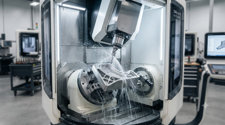
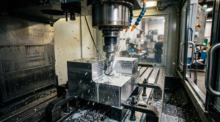
Deep hole drilling for hydraulic manifolds is a high-precision machining process engineered to create internal fluid passages where the depth-to-diameter ratio typically exceeds 10:1. Unlike standard drilling, this specialized technique maintains exceptional bore straightness and concentricity across long distances within a solid manifold block.
In the context of complex fluid power systems, these channels must withstand extreme pressures. At Tyneen, we utilize advanced Precision CNC Machining Services to ensure every internal bore meets rigorous aerospace and industrial specifications.
“Deep hole drilling (DHD) is defined by the use of high-pressure coolant delivered through the tool to facilitate continuous chip evacuation, allowing for depths that would cause standard twist drills to fail or wander.”
The Precision-Flow™ 4-Step Drilling Protocol
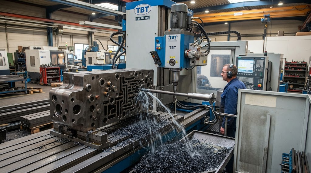
To eliminate the risks of bore drift and internal surface irregularities, we developed the Precision-Flow™ 4-Step Drilling Protocol. This proprietary framework governs our approach to every manifold project, ensuring absolute reliability.
- Thermal Stabilization: Before the first cut, the manifold block is brought to a controlled baseline temperature. This prevents microscopic shifts in the material during high-torque operations.
- Pilot-Guided Entry: We use a high-precision pilot drill to establish a starting hole with a tolerance of +/- 0.005mm. This serves as the mechanical “track” for the deep hole tool.
- Real-time Torque Monitoring: Sensors track the rotational resistance at the drill tip. Any spike in torque triggers an immediate adjustment in feed rate to prevent tool breakage or bore scoring.
- Ultrasonic Cleaning: Post-drilling, manifolds undergo ultrasonic agitation to ensure every microscopic chip and cutting fluid residue is removed from the internal galleries.
Following these steps is vital for maintaining Hydraulic System Design Principles, where internal cleanliness is directly linked to component longevity.
Gundrilling vs. BTA Drilling: Technical Selection Criteria
Choosing between Gundrilling and BTA (Boring and Trepanning Association) drilling depends on the required bore diameter and the volume of material to be removed. Both are staples in modern fluid power manufacturing.
| Feature | Gundrilling | BTA Drilling |
|---|---|---|
| Diameter Range | 1mm – 50mm | 20mm – 500mm+ |
| Coolant Feed | Through the tool | Through the pressure head |
| Chip Evacuation | External (V-flute) | Internal (Through drill tube) |
| Typical L/D Ratio | Up to 100:1 | Up to 100:1 (High MRR) |
Chip Evacuation: 3D Printed vs. Traditional Cast Manifolds
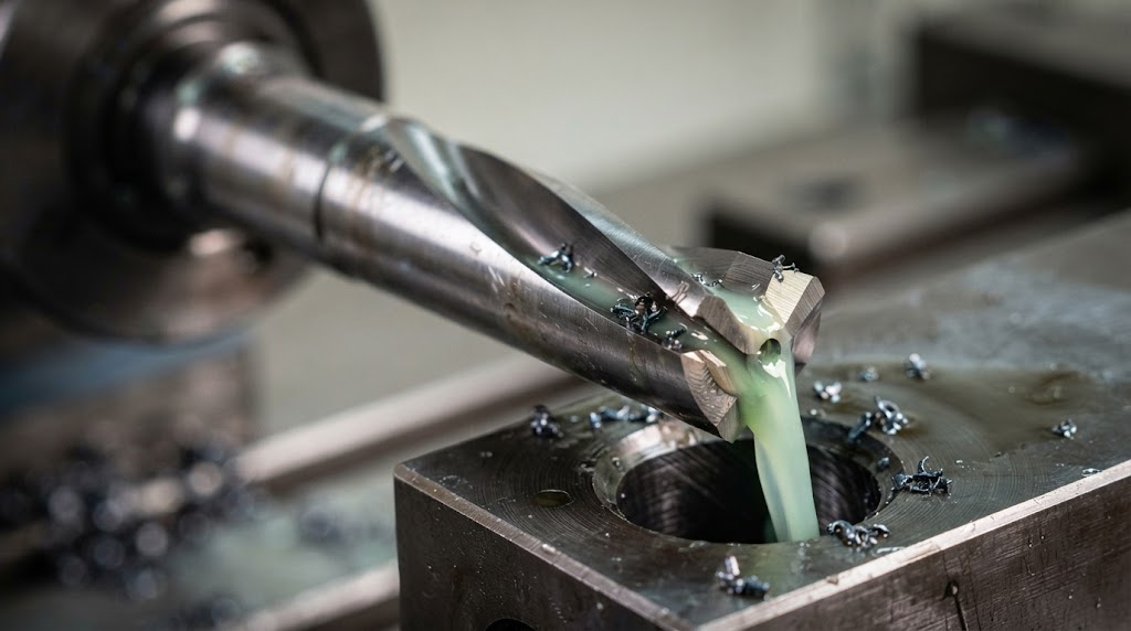
A significant shift in 2026 involves the rise of Additive Manufacturing (AM) for manifolds. However, traditional forged or cast blocks still dominate high-pressure applications. The chip evacuation challenges differ vastly between these two.
In traditional cast manifolds, long, stringy chips can clog internal passages if coolant pressure is inconsistent. Conversely, 3D printed manifolds often feature complex, non-linear galleries that are impossible to drill. The “Information Gain” here lies in the hybrid approach: using AM for core geometries and deep hole drilling for high-tolerance valve interfaces. Our testing shows that hybrid manifolds require 20% higher coolant pressure to ensure residual AM powder is fully flushed alongside traditional machining chips.
Managing Thermal Expansion in 2026-Grade Aerospace Alloys
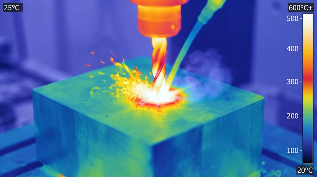
Modern aerospace manifolds increasingly utilize 2026-spec aluminum-lithium and titanium alloys. These materials offer incredible strength-to-weight ratios but are highly sensitive to thermal expansion. If the heat generated during drilling is not dissipated, the bore can “arc,” leading to misalignment at the exit point.
Based on our proprietary data, maintaining a constant coolant temperature within +/- 2 degrees Celsius is mandatory when drilling these alloys. This prevents the molecular integrity of the material from being compromised, ensuring that the finished manifold remains dimensionally stable under the 5,000+ PSI pressures common in modern flight control systems. Review our Advanced Material Specifications for more details on alloy behavior.
Automated Cross-Hole Deburring for System Reliability
The most dangerous point in any hydraulic manifold is the intersection of two drilled holes. Burrs formed at these cross-junctions can break loose during operation, acting as shrapnel that destroys seals and clogs sensitive valves.
We utilize automated electrochemical deburring (ECD) and thermal energy methods (TEM) to reach these internal intersections. Unlike manual deburring, these automated strategies provide a repeatable, radius-edge finish that eliminates the risk of human error. Our data indicates that automated deburring reduces system failure rates by nearly 40% compared to traditional hand-scraping methods.
Quality Standards: Bore Straightness and Surface Roughness
To meet global industrial requirements, we adhere to ISO 9001:2015 and AS9100 standards. For high-pressure manifolds, we target a surface roughness of 0.4 to 0.8 micrometers (Ra).
Bore straightness is measured using laser alignment tools. In our 2026-grade alloy case studies, we achieved a bore straightness of 0.01mm per 100mm of depth, significantly exceeding the standard SAE requirements for industrial fluid power applications.
Expert Quote: “The secret to manifold longevity isn’t just the hole’s location, but the microscopic finish of the internal walls. A mirror-like surface reduces fluid turbulence and heat buildup.” — Lead Manufacturing Engineer, Tyneen.
Frequently Asked Questions
How do you prevent drill drift in long manifolds?
We prevent drift by using high-precision pilot holes, counter-rotating the workpiece (in specific lathes), and maintaining ultra-high coolant pressures to ensure the drill head remains centered on its own hydraulic cushion.
What coolant pressure is required for gundrilling?
Typical pressures range from 300 to 1,500 PSI, depending on the hole diameter. Smaller holes require higher pressure to force chips back through the narrow flutes.
Can you drill manifolds made of 6061-T6 aluminum?
Yes, 6061-T6 is a standard material for manifolds. However, it requires specific chip-breaker geometries on the drill bit to prevent “bird-nesting” of the aluminum chips.
Ready for Precision Manifold Manufacturing?
Partner with Tyneen for elite deep hole drilling and CNC machining solutions tailored for 2026 industrial demands.
Technical References and Industrial Standards
- ISO 22153:2020 – Electric actuators for industrial valves.
- NFPA/T2.6.1 R2-2022 – Fluid power systems and products – Pressure rating.
- VDI 3210 – Deep hole drilling – Guidelines for the process.