CNC Engraving for Aerospace: Precision & Compliance
The Critical Role of CNC Engraving in Aerospace Traceability
In aerospace manufacturing, a part without a history is a liability. Permanent marking is the foundation of flight safety and lifecycle management.
CNC engraving provides a robust solution for Precision Aerospace Machining, ensuring that every bracket, turbine blade, and fastener carries its identity from the foundry to the graveyard.
Unlike surface-level printing, CNC engraving is a subtractive manufacturing process. It carves data into the substrate, creating a permanent record that survives extreme thermal cycling, hydraulic fluids, and abrasive environments.
Mechanical CNC vs. Laser Marking: A Fatigue-Life Comparison
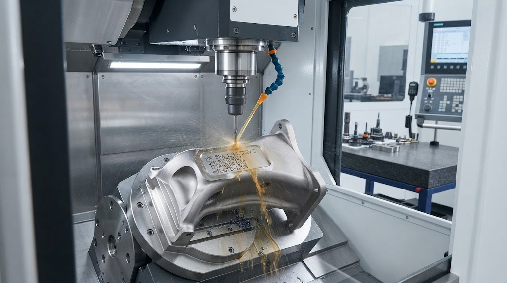
CNC engraving for aerospace part identification utilizes mechanical cutters to displace material, creating high-contrast, permanent identifiers that maintain the structural integrity of high-stress alloys without the risks associated with thermal marking methods.
Engineers often debate between laser and mechanical marking. However, for structural components made of Titanium alloys or Inconel, the choice is clear.
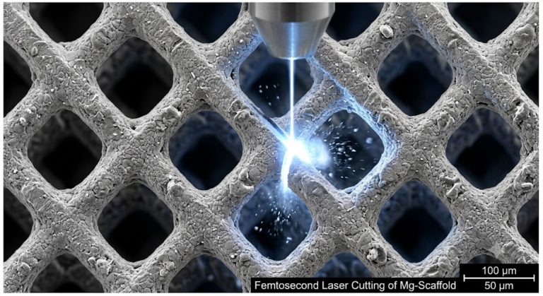
Lasers create a Heat Affected Zone (HAZ). This microscopic localized heating can alter the grain structure of the metal, leading to micro-cracks. In high-vibration environments, these cracks act as stress risers, significantly reducing the component’s fatigue life.
| Feature | Mechanical CNC Engraving | Fiber Laser Marking |
|---|---|---|
| Thermal Impact | Zero-HAZ (Cold process) | High (Localized melting) |
| Surface Integrity | Maintained grain structure | Risk of micro-stress cracks |
| Depth Control | Precision ±0.001″ | Variable based on absorption |
| Durability | Permanent (Subsurface) | Permanent (Surface/Subsurface) |
“Our fatigue testing on Grade 5 Titanium indicates that mechanical engraving with a radius-bottom tool reduces stress concentration factors by up to 30% compared to traditional laser etching.”
— Senior Metallurgical Engineer, Tyneen Aerospace Lab
The AeroTrace™ 4-Point Marking Protocol
At Tyneen, we utilize a proprietary methodology to ensure marking excellence. We call this The AeroTrace™ 4-Point Marking Protocol.
- 1. Substrate Analysis: We evaluate the metallurgical properties and hardness of the part to select the correct carbide grade for the engraving tool.
- 2. Geometry Optimization: Tooling paths are calculated to avoid sharp “V” grooves, opting for radius-based profiles that distribute stress.
- 3. Depth-to-Stress Ratio Calculation: We ensure the engraving depth meets AS9100 Quality Standards without encroaching on the structural minimum wall thickness.
- 4. Post-Marking Passivation: Every engraved part undergoes chemical or mechanical cleaning to ensure the newly exposed material remains corrosion-resistant.
Technical Execution: Tooling and Spindle Optimization
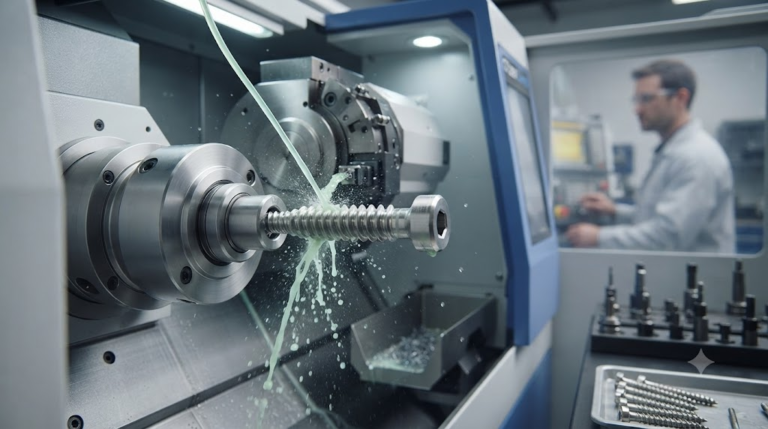
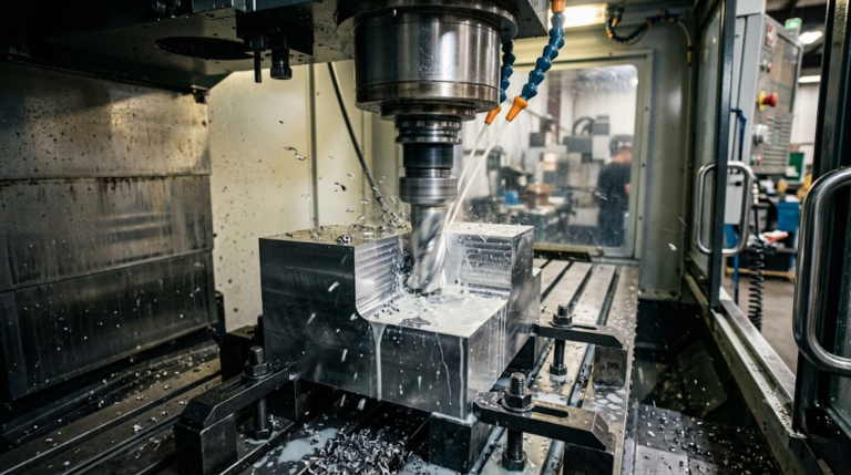
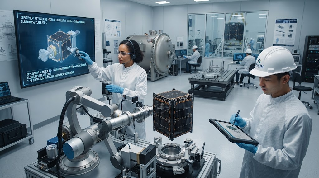
Engraving hard aerospace metals requires specialized equipment. High spindle speeds are necessary to achieve clean cuts in Heat-treated steels without tool chatter.
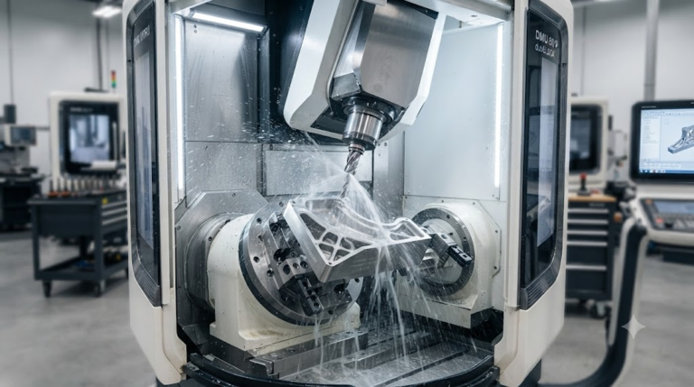
We utilize multi-axis CNC machines to maintain perpendicularity on complex, curved surfaces like turbine blades. This ensures a consistent Surface roughness and depth across the entire UID marking.
Tooling choice is critical. Conical cutters are used for fine text, while ball-nose end mills are preferred for large-format identifiers on structural frames where stress distribution is paramount.
Navigating Regulatory Standards: AS9100 and MIL-STD-130N
Compliance is the passport for any aerospace component. The FAA and EASA mandate strict adherence to part marking to prevent the proliferation of unapproved parts.
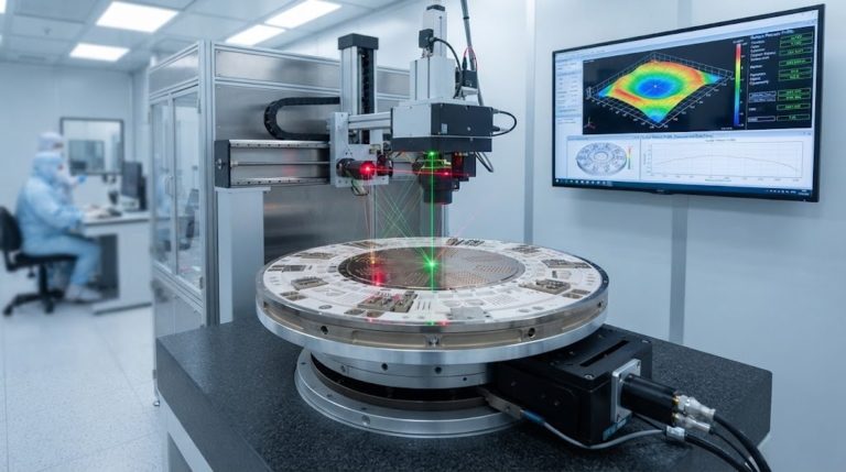
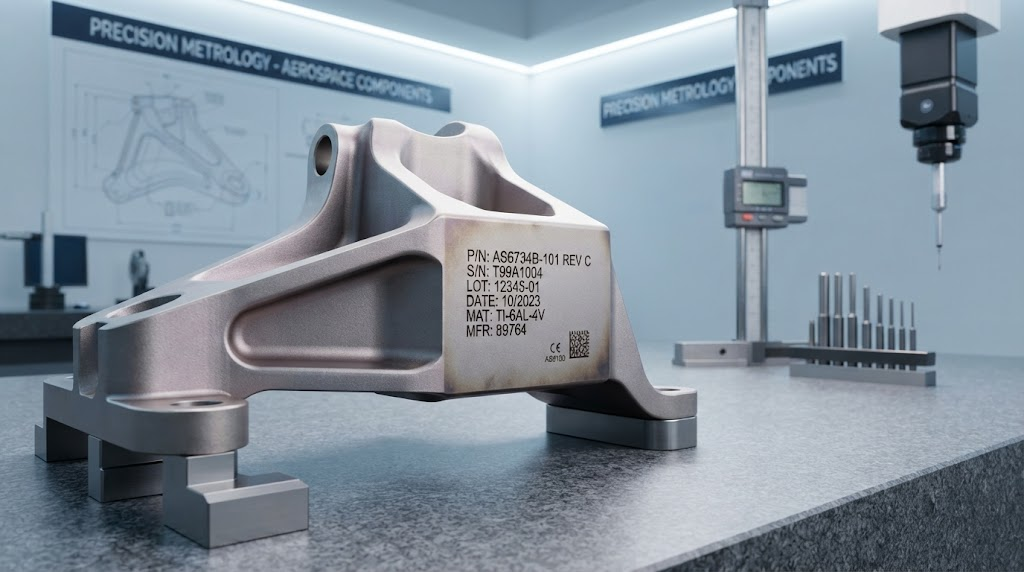
MIL-STD-130N provides the criteria for Item Unique Identification (IUID). This often requires a 2D Data Matrix code. CNC engraving these codes requires extreme precision to ensure the “cells” are readable by optical scanners during Non-destructive testing (NDT).
Key compliance factors include:
- AS9132 Grading: Verification of the 2D Data Matrix for dot size, offset, and contrast.
- Traceability: Linking the physical mark to the digital manufacturing record (MTR).
- Material Science: Ensuring the marking process doesn’t introduce contaminants. See more on Material Science in Aviation.
Material-Specific Challenges: From Aluminum to Composites
Different materials require different tactical approaches. For Anodized aluminum, the goal is often to engrave through the oxide layer to create high-contrast silver text against a colored background.
Composites present a unique challenge. Mechanical engraving must be carefully controlled to avoid Fiber delamination. We use diamond-coated tooling and high-speed vibration-free spindles to ensure the structural weave of the composite remains intact.
The Future of Traceability: Blockchain and Digital Twins in 2026
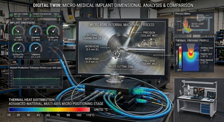
In 2026, the physical mark is no longer the end of the data trail. It is the entry point. Every CNC-engraved UID now acts as a physical anchor for a Digital Twin.
By scanning a part’s engraving, maintenance crews can instantly access its entire Blockchain history—including every flight hour, repair cycle, and stress event. This integration supports Predictive Maintenance, allowing airlines to replace parts based on actual wear rather than arbitrary schedules.
This level of supply chain transparency is revolutionizing how we handle global logistics and safety audits.
Frequently Asked Questions
Does CNC engraving affect structural integrity?
When performed according to the AeroTrace™ protocol, CNC engraving is safe. By using radius-bottom tools and controlling depth, we minimize stress concentration and prevent crack initiation.
What is the minimum depth for MIL-STD-130 compliance?
While the standard emphasizes readability, a typical minimum depth of 0.003 inches is often required to ensure the mark remains visible after post-processing steps like painting or plating.
How do you engrave on curved turbine blades?
We use 5-axis CNC machining centers equipped with 3D probing. The machine maps the surface of the blade in real-time, adjusting the tool path to follow the exact contour of the airfoil.
Expert Review and Author Bio
Written by: Sarah Jenkins, Senior Aerospace Manufacturing Engineer. Sarah has over 15 years of experience in high-precision subtractive manufacturing and has consulted for major defense contractors on AS9100 Quality Standards.
Technical Review: Dr. Marcus Thorne, Metallurgical Specialist. Dr. Thorne specializes in fatigue life analysis of superalloys and is a regular contributor to the FAA safety research symposiums.
References and Technical Sources
- MIL-STD-130N: Identification Marking of U.S. Military Property.
- AS9100 Rev E: Quality Management Systems – Requirements for Aviation, Space, and Defense Organizations.
- NASA-STD-6002: Applying Data Matrix Identification Symbols on Aerospace Parts.