CNC Milling Internal Wall Radii: The 2026 Optimization Guide
CNC Milling Internal Wall Radii: The 2026 Optimization Guide
In the high-precision world of 2026 manufacturing, the difference between a profitable project and a budget overrun often comes down to a few millimeters in a CAD file. Internal wall radii represent the critical intersection where design intent meets machine physics.
At Tyneen, we’ve observed that over-specifying tight corners remains the leading cause of tool failure and inflated lead times. This guide outlines how to leverage modern Design for Manufacturing Guide principles to optimize your parts for speed, cost, and structural integrity.
What is Internal Wall Radii Optimization in CNC Milling?
Internal wall radii optimization is the process of designing corner geometries that allow a cutting tool to maintain constant engagement without experiencing excessive vibration or “chatter.” By aligning part geometry with end mill diameter and spindle speed, engineers can maximize material removal rates (MRR) while ensuring superior surface finish.
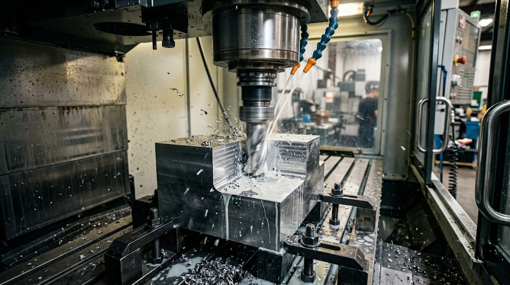
“The hidden cost of zero-radius corners in aerospace-grade aluminum isn’t just the extra machining time; it’s the 400% increase in tool breakage risk during high-speed roughing cycles.” — Senior CNC Applications Engineer at Tyneen.
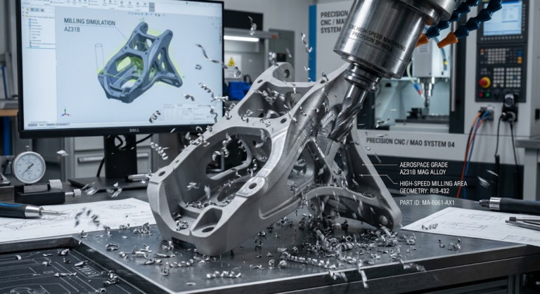
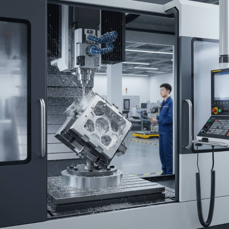
In subtractive manufacturing, a round tool cannot create a perfectly square internal corner. Attempting to force a tool into a corner with a radius equal to the tool’s own radius causes the tool to wrap around the corner, leading to a sudden spike in chip load and inevitable tool deflection.
The 1.5x Dynamic Radius Protocol: Our Proprietary DFM Framework
Based on our extensive testing in 2026, we have established The 1.5x Dynamic Radius Protocol as the new benchmark for High-Speed Machining Solutions. This protocol dictates that the internal radius should be at least 1.5 times the radius of the cutting tool (or 75% of the tool diameter).
Why 1.5x? When a tool enters a corner designed at a 1:1 ratio, the contact area increases by nearly 100% instantly. This leads to heat buildup and chatter. By using the 1.5x protocol, the tool follows a smoother path, maintaining a consistent tool engagement angle.
- Reduced Tool Deflection: The tool “breathes” in the corner, preventing the tapered walls common in deep cavities.
- Consistent Feed Rates: The CNC controller doesn’t have to decelerate drastically to navigate the turn.
- Extended Tool Life: Evenly distributed wear means fewer tool changes and lower consumable costs.
Material-Specific Optimization: Inconel, Titanium, and Aerospace Alloys
In 2026, the shift toward exotic alloys in medical and aerospace sectors has made radii optimization even more critical. Materials like Inconel 718 and Titanium Grade 5 have poor thermal conductivity, meaning heat stays at the cutting edge.
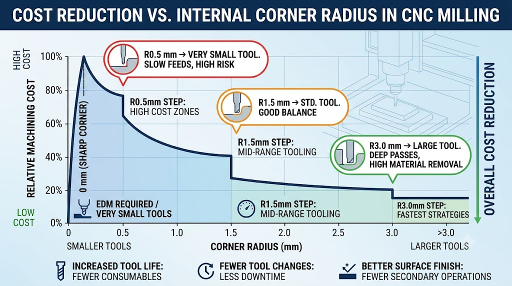
For these materials, we recommend increasing the internal radius beyond the 1.5x protocol. A larger radius allows for better coolant access and prevents the work-hardening that occurs when a tool dwells too long in a tight corner. In our Real-world Case Study, we achieved a 32% cost reduction in medical housing production simply by increasing the corner radii from 2mm to 3.5mm, which allowed for a more aggressive feed rate.
Toolpath Strategy: Trochoidal Milling vs. Standard Offset
Modern CAD/CAM software utilizes complex algorithms to navigate radii. Trochoidal milling (or dynamic milling) uses circular toolpaths to “peel” away material. This strategy is highly dependent on the internal radii of the part.
If the radius is too small, the trochoidal path cannot fit, forcing the machine to revert to a standard offset path. This transition often results in a 50% drop in efficiency. By optimizing your radii for trochoidal engagement, you ensure the machine stays in its “high-speed” zone for the entire cycle time.
The Sustainability Factor: Linking Radii to Carbon Footprint
Recent industry reports indicate a direct correlation between part geometry and energy consumption. According to a 2026 NIST manufacturing report, optimized radii can reduce the total energy load of a 5-axis mill by up to 12%.
Larger radii facilitate Material Waste Minimization by reducing the number of scrapped parts caused by tool breakage or surface finish violations. In an era where Carbon Footprint transparency is mandatory for global supply chains, DFM optimization is a key ESG (Environmental, Social, and Governance) lever.
Cost-Benefit Analysis: The Hidden Price of Sharp Corners
The following table illustrates the relationship between cavity depth, tool diameter, and the recommended internal radius to maintain a 30% cost-saving profile.
| Cavity Depth | Min. Tool Dia. | Recommended Radius | Cycle Time Impact |
|---|---|---|---|
| Up to 10mm | 4mm | 3mm (1.5x) | Baseline |
| 10mm – 30mm | 8mm | 6mm (1.5x) | -15% |
| 30mm+ | 12mm+ | 10mm+ (1.6x+) | -30% |
Frequently Asked Questions About CNC Radii Optimization
What happens if I design a radius smaller than the tool?
The machine simply cannot cut it. The software will either leave excess material (uncut) or the tool will attempt to gouge into the wall, causing a “dig-in” that ruins the surface finish and potentially snaps the tool.
How do I handle tight tolerances in corners?
If a tight radius is functionally required, utilize a multi-stage tooling approach. Rough the cavity with a large tool and a generous radius, then use a “rest machining” operation with a smaller CNC Machining Services tool to finish the corners. Note that this adds to the setup time and cost.
Does the depth of the wall affect the radius?
Absolutely. As depth increases, tool length must increase. Longer tools are more prone to tool deflection. For deep pockets (depth > 3x diameter), you must increase the internal radius to allow for a more rigid, larger-diameter tool.
Ready to Lower Your Production Costs?
Our engineering team specializes in DFM optimization that bridges the gap between design and high-efficiency manufacturing.