Safe Magnesium CNC Machining: NFPA 484 Precision Guide
Machining these structural lightweights introduces severe chemical and physical challenges. Fine magnesium turnings, micro-swarf, and airborne particulates exhibit high pyrophoric and deflagration tendencies. Any deviation from strict thermal and mechanical safety boundaries risks rapid thermal runaway.
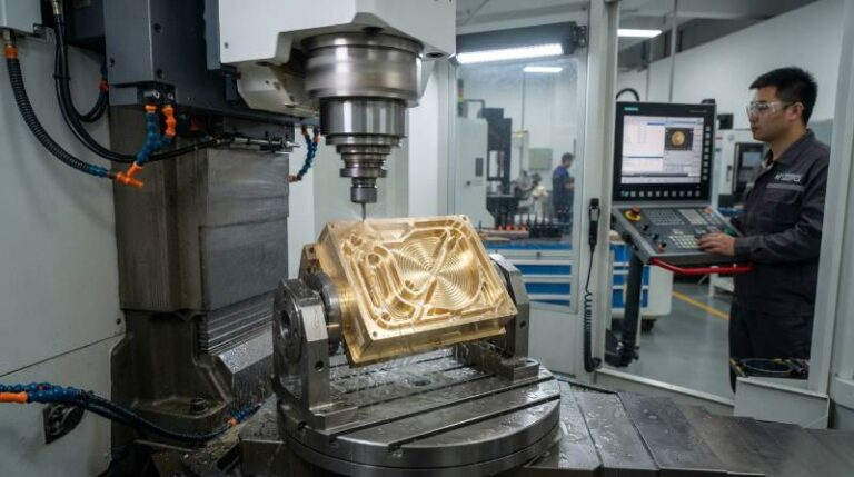
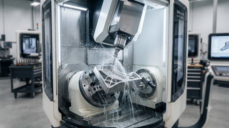
Navigating standards like NFPA 484 (and its consolidation into NFPA 660) is non-negotiable for precision CNC production. At Tyneen, compliance and high-speed precision operate together. Our facility integrates strict explosion-mitigation protocols with advanced 5-axis DMG MORI platforms to produce flight-critical components held to tolerances of ±0.005 mm.
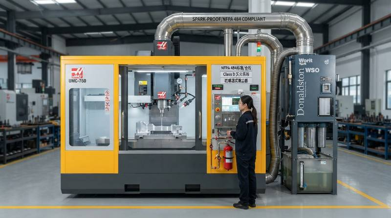
NFPA 484 Magnesium Machining Compliance & Safety Risk Framework
The National Fire Protection Association codifies combustible metal handling under NFPA 484 (Standard for Combustible Metals, Metal Powders, and Metal Dusts), transitioning into NFPA 660. The framework dictates strict material segregation, engineering controls, and proactive housekeeping.
“A combustible metal dust is defined as any particulate metal solid that can burn or ignite when dispersed in air. Any magnesium chip, particle, or fragment with a dimension smaller than 500 μm (0.05 mm) presents severe deflagration and explosive flash risks.” — NFPA Standards Technical Committee
Machining operations must consistently keep chip geometry outside this combustible dust envelope. Thin, paper-like chips or abrasive dust generate dangerous surface-area-to-volume ratios, lowering the activation energy required for rapid auto-ignition.
| Control Domain | Engineering Specification | Mandatory Compliance Target |
|---|---|---|
| Particle Geometry | Minimum chip thickness regulation | Average thickness > 500 μm (feed ≥ 0.10 mm/tooth) |
| Particulate Extraction | Wet scrubber hydro-filter ventilation | Spark-proof blowers, ducted airflow velocity ≥ 23 m/s |
| Atmospheric Pressure Relief | Explosion venting & burst discs | Calculated venting ratio per NFPA 68 structural standards |
| Operational Housekeeping | Chip recovery and storage cycles | Sealed, vented heavy-gauge steel bins; ≤ 4-hour clearing cycles |
Machining cells must avoid common dry collection systems. Standard baghouses or cyclonic cartridge collectors can form explosive dust clouds inside ducts. Instead, wet-scrubber systems submerge airborne particles into an engineered water bath immediately at the enclosure interface, preventing hazardous dust accumulation.
Understanding the Magnesium Fire Hazard: Exothermic Chemistry & Ignition Limits
Magnesium’s high chemical reactivity drives its fire risks during cutting. Conventional flood coolants contain water-based emulsions that react aggressively with fresh, unoxidized magnesium surfaces. This generates flammable hydrogen gas:
Exothermic chemical dissociation yielding highly explosive diatomic hydrogen gas and caustic magnesium hydroxide.
Trapped pockets of hydrogen inside high-speed CNC enclosures can reach lower explosive limits (LEL 4.0% vol in air) within minutes. An intermittent spark from tool wear or mechanical rub will instantly ignite this hydrogen pocket, triggering secondary ignition of hot magnesium chips.
Auto-Ignition Thresholds Across Engineering Alloys
Solid, wrought magnesium blocks typically auto-ignite near their melting points around 650°C. However, high-surface-area chips, feather swarf, and fines ignite at significantly lower temperatures, often near 450°C.
- AZ31B (3% Al, 1% Zn): General-purpose wrought alloy. Solid ignition point is 630°C. Fine turnings can combust around 450°C to 480°C under continuous frictional rubbing.
- AZ91D (9% Al, 1% Zn): High-strength die-cast/machining alloy. Melting begins at 470°C; fines and micro-dust burn readily if chips rub against dull flank faces.
- WE43 (4% Yttrium, 3% Rare Earths): Advanced aerospace alloy. Engineered yttrium-rich oxide skins boost solid-state flame resistance up to 750°C, though sub-500 μm fines still require standard NFPA containment.
- Elektron 21 (Neodymium-Zinc-Zirconium): Ultra-high-performance aerospace alloy. It resists ignition up to melting points, yet cutting friction above 500°C can ignite ultra-fine chips.

Coolant Selection Protocol: Dry Machining vs. High-Flashpoint Mineral Oils
Selecting the right cutting medium determines thermal control and safety when processing magnesium. Water-miscible synthetic or soluble emulsions are strictly prohibited by NFPA standards due to hydrogen release risks. Shops must choose between dry machining, chilled gas, or non-aqueous mineral oils.
1. High-Velocity Dry Machining
Dry machining eliminates fluid recycling complexity and chemical waste. It relies on clean, dry compressed air blasts or vortex tube cold air (-10°C to +5°C) to clear chips instantly from the cut zone. This prevents recutting, chip pack, and localized heat spikes.
2. High-Flashpoint Mineral Oils & Synthetic Esters
For high-precision, thin-walled work, dry cutting can introduce thermal drift. High-flashpoint, water-free mineral oils or synthetic ester cutting fluids are the industry standard here. NFPA 484 mandates that all cutting fluids used for magnesium feature a closed-cup flashpoint above 135°C (275°F).
Flooding the cut zone with pressurized mineral oil evacuates chips, suppresses sparks, lubricates the tool edge, and maintains constant workpiece temperature. Review our aerospace metal materials directory for detailed mechanical and thermal profiles across all production alloys.
3. Cryogenic Cooling (LN₂ and Supercritical CO₂)
Cryogenic machining delivers high cooling capacity without oxygen exposure. Directing liquid nitrogen (LN₂, -196°C) or liquid CO₂ through the spindle to the cutting edge freezes the shear zone, eliminates thermal growth, and displaces atmospheric oxygen, creating an inert envelope.
Class D Fire Extinguishers & CNC Cell Emergency Suppression Protocols
Water, foam, carbon dioxide, or Halon extinguishers must never be used on a magnesium fire. At temperatures above 800°C, burning magnesium splits carbon dioxide (2Mg + CO₂ → 2MgO + C), accelerating combustion. Water violently dissociates into hydrogen and oxygen, triggering a lethal deflagration.
| Extinguishing Agent | Chemical / Operational Basis | Safety Status |
|---|---|---|
| Water / Foam / Aqueous Solutions | Chemical reduction releasing H₂ gas + intensive boiling | PROHIBITED: Violent Explosion |
| Standard CO₂ / ABC Multi-Purpose | Magnesium burns in pure CO₂; ammonium phosphate feeds reaction | PROHIBITED: Exothermic Propagation |
| Sodium Chloride-Based Class D (Met-L-X) | Melts at ~800°C to form an oxygen-excluding crust | MANDATORY: Manual Suppression Standard |
| Copper-Based Powder (Class D – Lith-X) | Acts as a thermal heatsink, forms Cu-Mg eutectic layer | APPROVED: High-Temp Industrial Use |
| Argon / High-Purity Inert Gas Flood | Displaces oxygen inside the enclosed CNC volume | MANDATORY: Automated Cell Interlocking |
Per OSHA and NFPA requirements, portable Class D fire extinguishers must be positioned within 23 meters (75 feet) of all workstations cutting magnesium. Tyneen installs dedicated Class D units directly on machine chassis frames, backed by clean argon purge bottles piped into internal enclosures.
Precision CNC Tooling Geometry & Milling Parameters for Magnesium Alloys
Controlling heat starts with proper cutting tool geometry. Magnesium has low cutting resistance and high thermal conductivity. The goal is to maximize chip volume and evacuate chips quickly without excessive mechanical rubbing.
Vc: Cutting Speed (m/min), D: Cutter Diameter (mm), n: Spindle Speed (RPM), Vf: Table Feed Rate (mm/min), z: Flute Count, fz: Feed per Tooth (mm/tooth).
Tool Geometry Recommendations
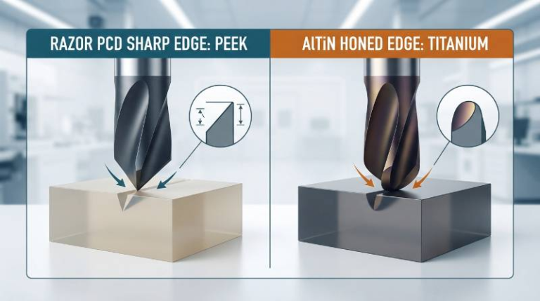
Dull cutting edges cause friction, work-hardening, and elevated temperatures. Tool designs should prioritize sharp geometry and open flutes:
- Rake Angle: High positive rake (+15° to +25°) reduces shear stress and localized tool temperatures.
- Relief Angle: Generous primary and secondary clearance (12° to 18°) prevents the cutting flank from rubbing across newly machined magnesium surfaces.
- Helix Angle: Moderate to high helix (30° to 45°) evacuates chips smoothly from deep cavities.
- Flute Count: 2-flute or 3-flute configurations maximize chip valley volume and avoid chip compression.
- Substrates & Coatings: Use micro-grain solid carbide. Polished uncoated flutes prevent built-up edge (BUE). For high-volume production, use Diamond-Like Carbon (DLC) or ultrathin mono-crystalline diamond coatings (never use AlTiN coatings, as aluminum-titanium compounds adhere to magnesium).
For more details on tooling approaches across our machines, visit our precision CNC milling capabilities.
| Machining Operation | Cutting Speed (Vc, m/min) | Feed per Tooth (fz, mm/tooth) | Axial Depth (ap, mm) |
|---|---|---|---|
| Heavy Roughing (Trochoidal) | 500 – 1200 | 0.15 – 0.35 | 1.5 × D (radial ae ≤ 15%) |
| Semi-Finishing | 600 – 1400 | 0.10 – 0.20 | 0.5 – 2.0 mm |
| Fine Finishing | 800 – 1800 | 0.08 – 0.15 | 0.1 – 0.3 mm |
Never take “dust cuts” or feather passes (ap < 0.05 mm or fz < 0.05 mm). Extremely thin passes rub the cutting edge against the stock, converting mechanical torque directly into frictional heat that can reach chip ignition thresholds.
The Tyneen Closed-Loop Combustible Metal Machining Architecture
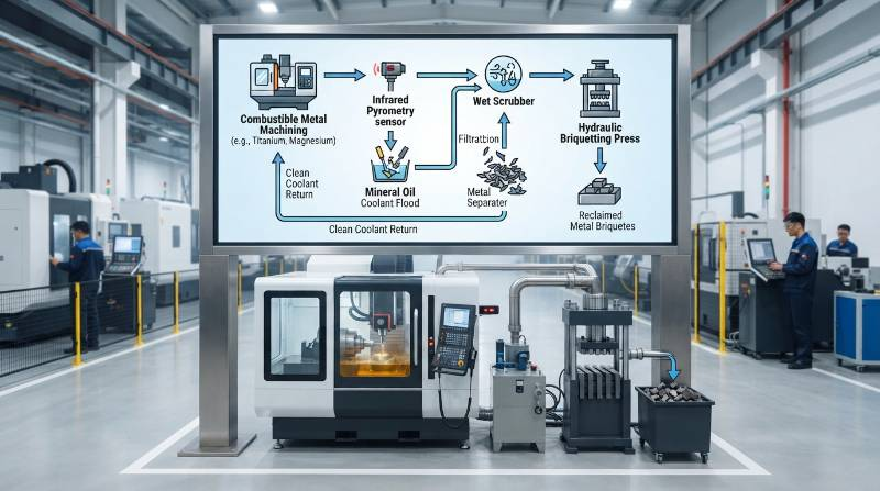
To safely scale precision magnesium production, Tyneen uses a proprietary four-tier closed-loop framework. This architecture mitigates deflagration risks while supporting micron-level accuracy.
- Stage 1: Real-Time Pyrometric Monitoring: Spindle-mounted non-contact infrared thermal sensors read contact zone temperatures continuously. If cutting temperatures exceed 180°C, the CNC kernel auto-pauses feed motions and floods the enclosure with argon.
- Stage 2: Pressurized Evacuation Delivery: Multi-nozzle manifolds output high-flashpoint mineral oil at 15 bar (220 psi) directly across all active cutting edges. This strips chips from the surface before tool engagement can cause rubbing.
- Stage 3: Spark-Proof Ducted Wet Scrubbing: Machine enclosures feature positive exhaust drawing at 26 m/s through grounded, conductive ductwork directly into a continuous wet hydro-filter unit. This converts airborne particulates into non-combustible wet sludge.
- Stage 4: Automated Chip Densification: Mechanical briquetters pull drained swarf from the chip conveyors and compact it into solid cylindrical pucks under 80 MPa of pressure. Removing entrapped oxygen stops spontaneous combustion in storage.
Ultra-Thin AZ31B 5-Axis Aerospace Housing Machining Benchmark
High-end avionics engineering demands severe weight reduction. Recently, Tyneen completed a mission-critical contract for a satellite avionics chassis manufactured from wrought magnesium AZ31B. This case study demonstrates our thermal and dimensional controls on complex parts.
Design and Machining Parameters
- Component: Multi-Bay Integrated Satellite RF Flight Chassis
- Raw Material: Forged Magnesium AZ31B-H24 per ASTM B107
- Final Part Envelope: 340 × 220 × 85 mm
- Minimum Wall Thickness: 0.70 mm (±0.015 mm) across deep bays
- True Position Callout: ⌀0.015 mm relative to datum structure A|B|C at maximum material condition
- Surface Roughness Requirement: Ra ≤ 0.4 μm across all interior RF cavities
Manufacturing Strategy and Metrology Execution
Magnesium’s high coefficient of thermal expansion (CTE ≈ 26 × 10⁻⁶/K) creates part deformation risks during machining. A temperature variation of 5°C across a 340 mm housing can cause 0.044 mm of thermal drift, which exceeds the allowed tolerance band.
Our team used 5-axis simultaneous DMG MORI machining centers fed by chilled mineral oil kept at exactly 20.0°C (±0.2°C). High-speed trochoidal roughing toolpaths maintained a constant tool engagement angle of 35°, keeping cutting forces and thermal loads stable.
For finishing deep 0.70 mm thin walls, custom balanced 2-flute DLC-coated carbide tools cleared chips without tool deflection. The completed chassis was pre-cleaned with solvent, vacuum-dried, and finished with Micro-Arc Oxidation (MAO) to create a corrosion-resistant, 15 μm ceramic barrier layer. Explore our wider capabilities in advanced CNC machining services.
Tyneen Certified Precision Infrastructure & Metrology Standards
Precision magnesium machining requires verified quality systems. Tyneen’s production facilities operate under ISO 9001:2015, IATF 16949, and AS9100D certifications, ensuring traceable, repeatable manufacturing workflows.
Metrology and Quality Systems
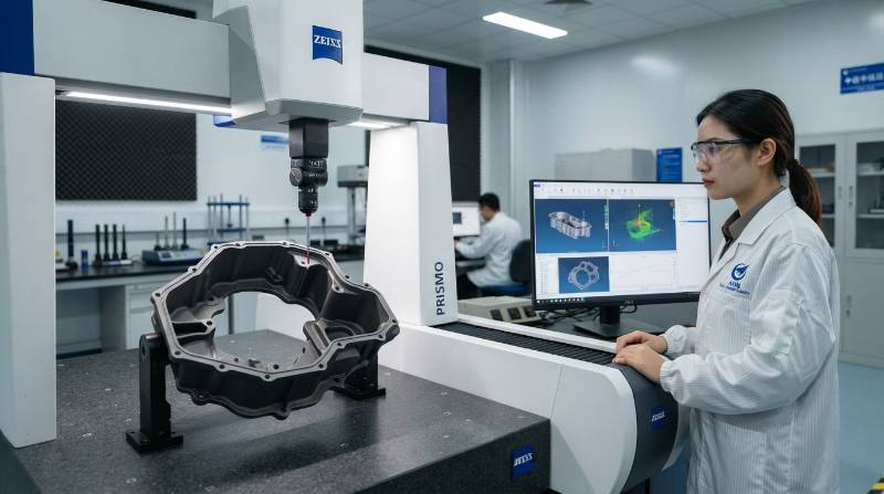
- Zeiss PRISMO Ultra Coordinate Measuring Machines (CMM): Real-time thermally compensated inspection capable of volumetric length measurement errors down to E₀ = 0.5 + L/500 μm.
- Optical 3D Surface Profilometry: Non-contact scanning confirms mirror-finish geometries down to Ra 0.2 μm without scratching soft alloy surfaces.
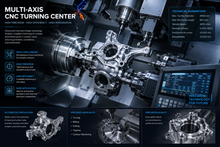
- Multi-Axis CNC Fleet: Simultaneous 3-axis, 4-axis, and 5-axis high-speed machining centers equipped with 24,000 RPM spindles and automated tool condition monitoring.
- Full Material Traceability: Every production lot includes full ASTM Material Test Reports (MTRs) and spectral chemical analyses verifying alloy purity.
Discover our turning facilities and multi-axis lathe operations via our dedicated CNC turning capabilities page.
Substantiating Quality: Engineering Comparisons & Verification Checklists
Engineers often evaluate magnesium against light structural alloys like aluminum 6061-T6. Comparing their mechanical properties shows why magnesium is worth the specialized machining safeguards:
| Engineering Metric | Magnesium AZ31B-H24 | Aluminum 6061-T6 | Practical Impact |
|---|---|---|---|
| Density (ρ) | 1.77 g/cm³ | 2.70 g/cm³ | 34% direct mass reduction |
| Elastic Modulus (E) | 45 GPa | 68.9 GPa | Lower stiffness; requires rib-stiffened geometry |
| Specific Stiffness (E/ρ) | 25.4 kN·m/g | 25.5 kN·m/g | Equivalent mass-to-rigidity performance |
| Relative Machinability | 500% (High speed, low power) | 100% (Industry baseline) | Low cutting forces, exceptional tool life |
| Damping Capacity | High (10× greater than 6061) | Low baseline resonance | Suppresses chatter; dampens sensitive optics |
| Coolant Flammability Risk | Severe under aqueous conditions | Zero ignition risk | Mandates NFPA 484 engineering protocols |
Anti-Corrosion Surface Finishing Checklist
Freshly cut magnesium oxidizes quickly and is prone to galvanic corrosion when paired with dissimilar metals. Quality sign-off requires verified downstream passivation and coatings:
- Chemical Degreasing: Remove residual mineral oils using mild, non-etching alkaline solvents (pH 9.0 to 11.0); never use strong acids.
- Fluoride Anodizing or Chemical Conversion: Apply chromate-free hexavalent-compliant conversion coatings (MIL-M-3171C Type VI) for baseline atmospheric protection.
- Micro-Arc Oxidation (MAO / PEO): Grow an in-situ ceramic dielectric layer (10 to 30 μm) in an alkaline electrolyte bath under high voltage (300 to 500 V). This boosts surface hardness beyond 1000 HV and passes 1,000+ hours of ASTM B117 salt spray exposure.
- Galvanic Isolation: Install wet primers or dielectric polymer washers (such as PTFE or 300-series passivated stainless hardware with zinc-nickel platings) at assembly joints to prevent bimetallic corrosion.
Frequently Asked Questions About Magnesium CNC Safety and NFPA Compliance
Can water-soluble coolants ever be used to machine magnesium?
No. Industrial codes and NFPA 484 prohibit standard water-miscible coolants for magnesium processing. The magnesium-water reaction releases flammable hydrogen gas. Machinists must use dry cutting methods with clean air blasts or water-free, high-flashpoint (>135°C) mineral oils.
How close must Class D fire extinguishers be placed relative to the CNC machine?
Per NFPA 484, approved Class D dry powder extinguishers must be positioned within an unobstructed travel distance of 23 meters (75 feet) from the machine envelope. Tyneen equips each magnesium machining cell with dedicated Met-L-X Class D units mounted directly on the enclosure framework.
How do you prevent thin-walled magnesium components from warping during cutting?
Magnesium’s low elastic modulus (45 GPa) makes it prone to deflection. Prevent spring-back and warping by taking light radial cuts, using high-helix polished tools (+20° rake), applying multi-axis trochoidal toolpaths, and running roughing-to-finishing relief cycles to release internal stresses.
What are the storage requirements for magnesium chips and swarf?
Magnesium chips must be gathered frequently and placed in clean, dry, covered steel containers marked for combustible metals. Containers must feature top-venting lids to prevent hydrogen buildup from ambient humidity and must be kept away from combustible materials in designated fire-safe areas.
3-Step Action Pathway: From CAD Review to Compliant Global Delivery
Precision aerospace and medical programs move fast. Tyneen streamlines the path from digital 3D models to NFPA 484-compliant magnesium parts through an agile, engineer-led production workflow:
Precision Magnesium Sourcing Engine
- Step 1: Secure CAD File Upload
Submit your native 3D CAD files (STEP, IGES, or Parasolid) alongside 2D GD&T drawings through our encrypted client portal. - Step 2: Automated DFM & Quote in Under 2 Hours
Our engineering team reviews your design for thin-wall limits, tool accessibility, and NFPA-compliant machining paths, returning an itemized quote and full DFM review. - Step 3: Precision Manufacturing & Global Dispatch
Parts are machined in our multi-axis centers, treated with advanced coatings (MAO/Anodizing), and verified on Zeiss CMMs. Shipments include full material test reports (MTR) and dimensional inspection data.