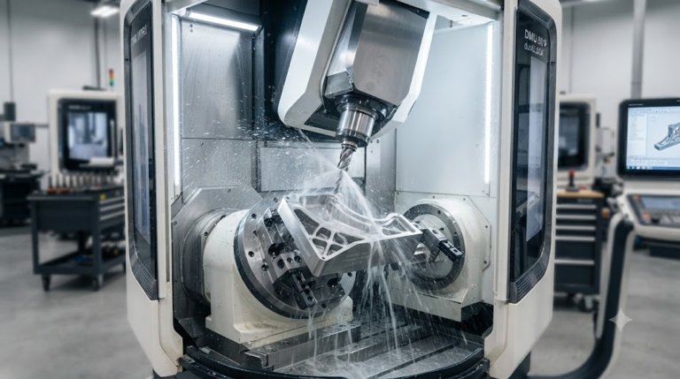
PEEK vs Titanium Medical Machining: An Engineer’s Guide
PEEK vs. Titanium in Medical CNC Machining: Executive Engineering Overview
Engineering medical-grade implants and structural surgical instruments demands uncompromising material integrity. Design teams frequently navigate the fundamental trade-off between polyetheretherketone (PEEK) and medical titanium alloys, specifically Ti-6Al-4V ELI (Grade 23).
Both materials fulfill critical biocompatibility mandates under ASTM F2026 (implantable PEEK) and ASTM F136 (wrought titanium alloy). However, their divergent mechanical profiles, thermal properties, and cutting kinematics require radically different manufacturing workflows.
Selecting between them dictates not only patient biomechanical outcomes, such as osseointegration rates and postoperative imaging clarity, but also production yield. Choosing verified, certified medical-grade CNC materials early in development avoids costly revisions during verification runs.
The Biomechanical & Machinability Decision Framework: Beyond Material Selection
Material evaluation for Class IIb and Class III medical devices extends beyond raw tensile figures. Engineering teams must weigh four foundational vectors: modulus matching to surrounding physiology, biological interface behavior, imaging diagnostics, and micro-machining precision.
Evaluation Framework Metric: Optimal implant design minimizes the delta between the material elastic modulus and native bone while maintaining machinability indexes capable of sub-10-micron dimensional repeatability without residual stress creep.
Biomechanical Comparison: Modulus Matching, Stress Shielding, and Bone Remodeling
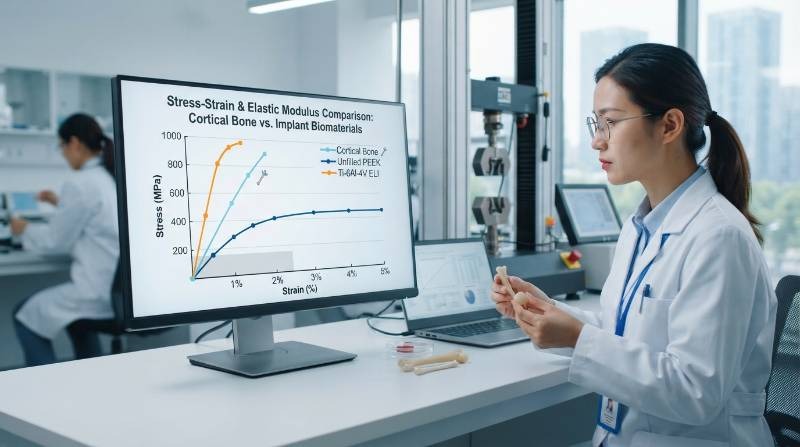
Cortical bone exhibits an elastic modulus between 10 GPa and 30 GPa, depending on anatomical location and patient density. Ti-6Al-4V ELI registers a high Young’s modulus of approximately 110 GPa.
This structural stiffness disparity often induces stress shielding. When a rigid metallic implant absorbs physiological mechanical loads, adjacent bone tissue experiences reduced strain, stimulating osteoclast-mediated bone resorption pursuant to Wolff’s Law.
Conversely, unfilled medical PEEK provides an elastic modulus of roughly 3.8 GPa. Carbon-fiber reinforced PEEK (CFR-PEEK) can be engineered to hit 18 GPa, closely mirroring natural cortical structures. By distributing cyclic physiological stresses back into surrounding bone, PEEK promotes ongoing remodeling and fusion.
However, titanium remains unmatched in load-bearing trauma plates and joint arthroplasty. Its tensile yield strength exceeds 860 MPa, whereas unfilled PEEK offers approximately 95 MPa to 100 MPa.
Biological Integration & Surface Interface: Osseointegration vs. Bio-Inertia
Titanium naturally passivates upon atmospheric exposure, forming a stable titanium dioxide (TiO₂) film. This chemically receptive layer promotes osteoblast migration, enabling direct osseointegration along the implant boundary.
PEEK exhibits extreme bio-inertia and hydrophobicity. While this inert chemistry prevents foreign-body reactions and cellular toxicity, it can limit cellular adherence, occasionally encapsulating unenhanced implants in fibrous tissue.
To overcome this, medical component designers specify complex surface texturing, titanium plasma sprays (TPS), or porous acid-etched geometries complying with ASTM F86 protocols.
Diagnostic Visibility & Radiographic Imaging: Radiolucency vs. Scatter Artifacts
Postoperative monitoring represents a critical dimension where polymer and metal diverge completely. Medical-grade PEEK demonstrates natural radiolucency across X-ray, computed tomography (CT), and magnetic resonance imaging (MRI) modalities.
This optical transparency enables surgeons to inspect spinal fusion progress, bone bridge growth, and soft tissue interfaces without visual obstruction. Radiologists can also accurately check for tumor recurrences adjacent to implant sites.
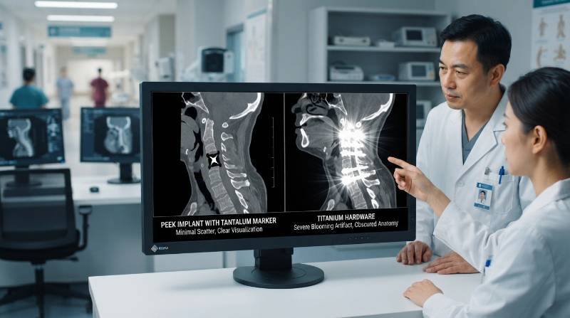
Titanium generates significant scattering artifacts, beam hardening, and signal blooming on CT and MRI diagnostics. These distortions frequently obscure margins at the device-tissue interface.
To maintain diagnostic visibility while tracking PEEK hardware location, CNC machinists press-fit micro radio-opaque markers. Tyneen regularly machines interference-fit pockets down to ⌀0.5 mm (±0.005 mm) to house medical-grade tantalum pins within structural PEEK implants.
Thermal Dynamics & CNC Tooling Strategies: Machining PEEK vs. Grade 23 Titanium
Thermal management is the defining challenge during high-precision cutting. Medical polymers and high-strength alloys present opposing thermal mechanics at the tool-workpiece interface.
PEEK features an extremely low thermal conductivity of roughly 0.25 W/m·K alongside a glass transition temperature (Tg) of 143°C. Heat generated during cutting stays trapped in the shear zone instead of transferring into chips.
Excess localized temperatures cause gummy plastic deformation, edge buildup, and severe micro-burring. Executing tight-tolerance cuts requires advanced precision machining services configured with chilled, oil-free air blasts to keep the cut zone below 100°C.
Ti-6Al-4V ELI exhibits low thermal conductivity for a metal (6.7 W/m·K) paired with high chemical reactivity at elevated temperatures. Cutting temperatures rapidly exceed 800°C at the cutting tip, accelerating crater wear, notch wear, and severe work hardening.
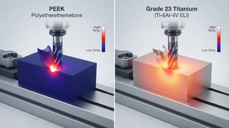
Thermal generation balance: Fc: Cutting Force (N), Vc: Cutting Speed (m/min), k: Thermal Conductivities (W/m·K)
Precision Tool Geometries, Speeds, Feeds, and Coolant Protocols
Tooling geometry must directly match the material’s failure mode:
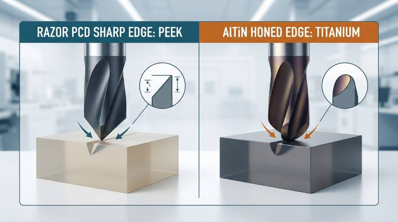
- PEEK Machining Strategy: Ultra-sharp, highly polished, uncoated micro-grain carbide or Polycrystalline Diamond (PCD) end mills. Positive rake angles (+10° to +15°) cleanly shear polymer chains without compressive distortion. Flood liquid coolant is typically avoided to eliminate residue contamination; filtered dry cold air blasts are preferred.
- Titanium Grade 23 Strategy: Rigid sub-micron carbide grades shielded by AlTiN or TiAlN Physical Vapor Deposition (PVD) coatings. Tough cutting edges with slight hone radii resist chipping. High-pressure through-spindle coolant delivery (≥ 70 bar) is essential to fragment chips and flush heat from the tool flank.
The Tyneen Bio-Thermal Precision Protocol: Stress Relief Annealing & Micro-Tolerance Control
Implantable PEEK contains semi-crystalline molecular zones that harbor severe internal stresses from extruded stock processing. Machining without controlled thermal conditioning leads to dynamic stress release, producing dimensional drift exceeding 0.05 mm days after final inspection.
To deliver true sub-micron stability, Tyneen enforces our proprietary Bio-Thermal Precision Protocol. This method incorporates a calibrated five-stage stress-relief cycle across manufacturing operations:

- Stage 1 (Pre-Machining Homogenization): Raw stock is heated to 150°C (above Tg), soaked for 4 hours, and brought slowly to 200°C to equalize core resin density.
- Stage 2 (Controlled Cooling): The material is cooled at an exact rate of ≤ 10°C per hour down to ambient temperature to lock in uniform crystallinity.
- Stage 3 (Semi-Finish Roughing): Components are roughed to within +0.3 mm of final design dimensions on 5-axis machines, relieving macro-level skin stresses.
- Stage 4 (Intermediate Stress Relief): A secondary thermal soak at 160°C relieves stresses induced by rough cutting passes.
- Stage 5 (High-Speed Finish Machining): Final finishing passes operate under low chip-load settings, holding critical dimensions within ±0.005 mm without subsequent creep.
Niche Scenario Benchmark: Thin-Walled Micro-Spinal Cages (Wall Thickness ≤ 0.4 mm)
Consider an expandable cervical interbody fusion cage requiring strut walls of ≤ 0.4 mm, deep gripping serrations, and diametrical pin-bore tolerances of ±0.005 mm with surface roughness of Ra ≤ 0.4 μm.
In PEEK, micro-end mills operating under excessive tool pressure push the 0.4 mm wall away rather than shearing it, inducing elastic rebound, taper defects, and entry-exit burrs. Tyneen addresses this by leveraging synchronized 5-axis CNC milling services that balance opposing cutting forces, using balanced multi-flute PCD tools run at high spindle speeds (up to 30,000 RPM) with micro-step feeds.
In Titanium Grade 23, the same 0.4 mm wall risks chatter and catastrophic work hardening if tool deflection causes cutter rub. Tyneen deploys dedicated precision Swiss CNC turning cells featuring synchronized dual-spindle support and sub-micron tool offsets, cutting parts in a single clamping phase.
Comprehensive Technical Comparison: Mechanical, Thermal, and Machining Validation Checklist
Use this direct engineering matrix to contrast key physical, mechanical, and machining specifications for medical-grade PEEK and Titanium:
| Property Parameter | PEEK (Unfilled, ASTM F2026) | Ti-6Al-4V ELI (Grade 23, ASTM F136) |
|---|---|---|
| Density (g/cm³) | 1.30 | 4.43 |
| Elastic Modulus (GPa) | 3.8 (Iso-elastic with bone) | 110 – 114 (High stiffness) |
| Tensile Yield Strength (MPa) | 95 – 100 | ≥ 860 |
| Thermal Conductivity (W/m·K) | 0.25 (Thermal insulator) | 6.7 (Moderate conductor) |
| Coefficient of Thermal Expansion (10⁻⁶/K) | 45 – 50 | 8.6 |
| Typical Cutting Speed Vc (m/min) | 150 – 300 | 40 – 70 |
| Primary Tooling Media | PCD / Polished Uncoated Carbide | AlTiN-Coated Micrograin Carbide |
| Autoclave Resistance (Steam cycles) | > 1,500 cycles | Indefinite |
| Radiographic Artifact Formation | Zero (Full radiolucency) | Severe beam hardening / scatter |
Tyneen Medical Machining Infrastructure: Multi-Axis CNC Fleet, Metrology, and Quality Systems
Machining implantable hardware demands absolute repeatability, continuous quality control, and pristine facility cleanliness. Tyneen maintains purpose-built medical machining cells backed by certified ISO 9001:2015, IATF 16949, and AS9100D quality frameworks.
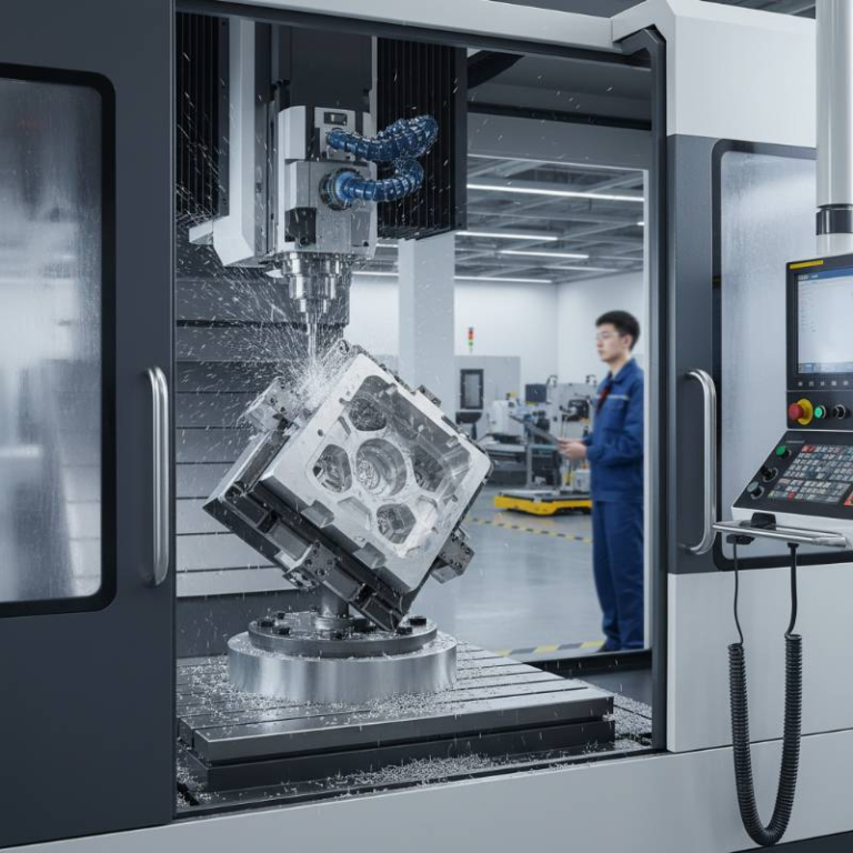
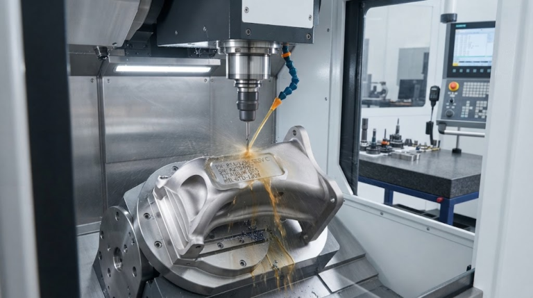
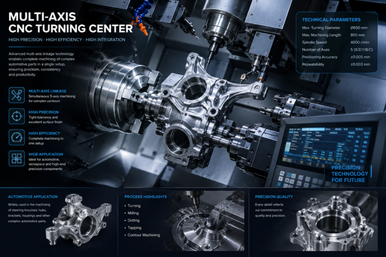
Our machining floor pairs DMG MORI 5-axis high-speed machining centers with Citizen and Star Swiss-type turning centers. These platforms utilize pressurized through-spindle cooling systems, oil mist collectors, and direct optical linear glass scales to deliver true ±0.005 mm positioning across continuous production runs.
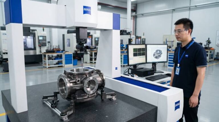
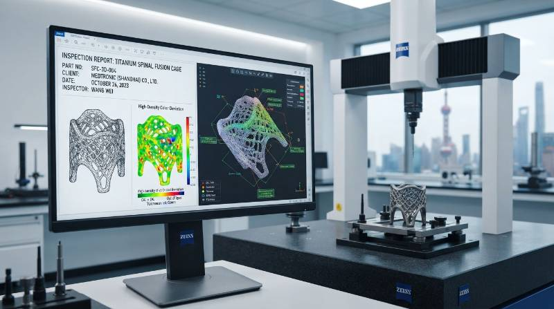
Metrology validation takes place in our dedicated climate-controlled quality laboratory (20°C ± 0.5°C). We verify geometry using Zeiss Coordinate Measuring Machines (CMM) with sub-micron scanning heads, Keyence optical comparators, and contact diamond-stylus profilometers to confirm surface finishes meet Ra ≤ 0.4 μm.
Every production lot includes 100% heat-lot traceability, validated Mill Test Reports (MTR), raw material certificates, and multi-stage ultrasonic degreasing logs to deliver clean, oil-free medical components ready for final packaging.
From CAD to Validated Implant: The 3-Step Tyneen Medical Manufacturing Pathway
Transitioning novel medical devices from design concepts to verified clinical hardware demands speed without regulatory compromise. Tyneen streamlines this development through a clear three-step pathway:
Launch Your Medical Machining Project with Tyneen
- Upload 3D CAD / STEP Model: Submit your component native CAD or STEP files alongside your 2D engineering drawings and GD&T requirements via our encrypted portal.
- DFM Analysis & Quote in 2 Hours: Receive a comprehensive Design for Manufacturability review assessing material dynamics (PEEK vs Titanium), tool access, and cost drivers with transparent pricing in under two hours.
- Production, Zeiss CMM Report & Fast Dispatch: Your components enter multi-axis CNC production, undergo full metrology inspection with Zeiss CMM verification, and ship globally with full ASTM/ISO certification records.
When you are ready to evaluate tolerances and production costs, request an engineering DFM review to consult directly with our biomedical machining team.
Technical Verification & Frequently Asked Medical Device Engineering Questions
Why is medical-grade PEEK component machining often more expensive than Titanium Grade 23?
While Titanium Grade 23 incurs higher tool wear costs, raw implantable-grade PEEK (such as Invibio PEEK-OPTIMA complying with ASTM F2026) commands a substantial raw-material premium, often exceeding 3,000 to4,500 per kilogram. Additionally, PEEK’s required multi-stage stress-relief annealing cycles extend furnace cycle times, adding controlled processing hours compared to standard titanium machining.
How do repeated hospital sterilization cycles affect machined PEEK vs. Titanium?
Both materials tolerate common hospital sterilization methods, including Ethylene Oxide (EtO) and low-temperature hydrogen peroxide gas plasma. Machined PEEK can survive more than 1,500 pressurized steam autoclave cycles (134°C) without significant tensile degradation. However, repeated high-dose gamma irradiation can induce chain scission in PEEK over time, whereas titanium remains unaffected by any ionizing radiation method.
What surface treatments are mandatory after machining titanium components?
Following CNC Swiss turning or milling, titanium parts undergo ultrasonic aqueous cleaning followed by chemical passivation in compliance with ASTM A967 or ASTM F86. Citric acid or nitric acid passivation dissolves microscopic embedded iron free-radicals left by cutting tools, restoring a uniform, fully passive titanium dioxide (TiO₂) film.
How does Tyneen eliminate microscopic burrs on flexible PEEK implant geometries?
Because abrasive blasting can impregnate polymer matrices with grit, PEEK components undergo cryogenic deflashing or microscopic hand deburring under 40x to 50x magnification using specialized micro-scalpels. Using razor-sharp PCD tools and precise toolpath entry angles during the primary CNC operation minimizes edge breakout, preventing burrs from forming at feature intersections.