How to Reduce CNC Machining Costs: An Engineering Guide
The Engineering Cost Breakdown: Evaluating CNC Machining Total Cost of Ownership (TCO)
Machining expenses are driven by physics and process economics. Understanding how to reduce CNC machining costs starts with an objective evaluation of spindle time, raw stock waste, workholding labor, and metrology overhead.
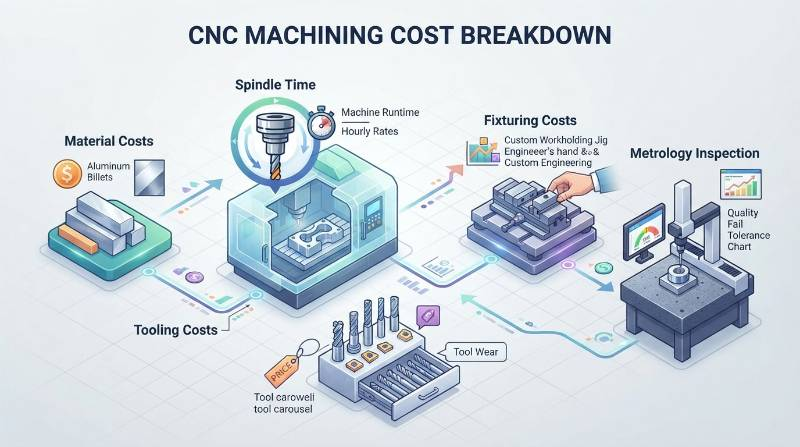
CNC Machining Total Cost of Ownership (TCO): The aggregate sum of raw billet expenditure, non-recurring engineering (NRE), spindle operational run rate ($/hour), consumable cutting tool depreciation, fixturing labor, and post-process quality verification.
A standard prismatic part produced on a 3-axis or 5-axis vertical machining center (VMC) exhibits the following typical cost profile:
- Spindle Runtime (40–55%): Direct cutting time determined by feed rates, depths of cut (DOC), step-overs, and tool engagement angles.
- Setup, Re-clamping & Fixturing (20–30%): Manual labor required to locate datums, align soft jaws, and reposition parts between operations.
- Raw Material & Scrap (15–20%): Initial stock sizing, volumetric chip removal percentage, and raw alloy pricing.
- Tool Wear & NRE Programming (10–15%): CAM toolpath generation, simulation, custom cutting tools, and automated Coordinate Measuring Machine (CMM) inspection programs.
The 5-Vector DFM Cost-Reduction Framework
Design for Machinability (DFM) must be structured across distinct mechanical disciplines. Unsystematic feature trimming rarely achieves sustainable unit savings.
The Five Dimensions of Machining Economy
- Geometric Simplification: Eliminating non-functional complex surfacing and standardizing internal radii to standard end mill profiles.
- Tolerancing Rationalization: Applying strict dimensional constraints solely to functional interfaces while using general international standards elsewhere.
- Setup Consolidation: Designing parts for multi-face access to minimize re-fixturing cycles and operator interventions.
- Material Machinability Alignment: Selecting the most machinable alloy grade capable of fulfilling thermal and structural load parameters.
- Batch & Nesting Optimization: Scaling production lots to dilute CAM programming and machine setup costs across multi-part tombstone fixtures.
CAD Geometry & Tooling Optimization: Cutting Cycle Times at the Design Stage
Machining cycle time directly dictates invoice cost. By optimizing CAD geometry for rotary cutting tools, engineers can eliminate custom cutters and slow step-over operations.
When engineering complex structural enclosures, using experienced precision CNC milling services ensures geometric features are milled using optimized trochoidal toolpaths rather than legacy, high-wear cutting strategies.
Internal Corner Radii and Pocket Depth Rules
Standard cylindrical end mills cannot cut sharp 90-degree internal vertical corners. Forcing a sharp internal edge requires secondary electrical discharge machining (EDM) or specialized micro-broaching, increasing feature costs by over 200%.
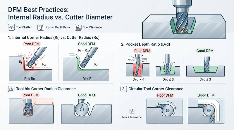
- Radius Sizing: Design internal vertical fillets at least 10% to 15% larger than the cutting tool radius (e.g., specify an R3.5mm corner radius for a standard R3.0mm / 6mm tool). This allows continuous corner engagement without causing tool chatter or deceleration.
- Depth-to-Diameter Ratios: Keep internal cavity depths within 3x to 4x of tool diameter. A depth exceeding 4x forces operators to reduce feeds and speeds by up to 70% to counteract tool deflection and thermal vibration.
- Uniform Wall Thickness: Maintain minimum wall thicknesses of 0.8mm for aluminum and 1.5mm for thermoplastics. Thin, non-uniform walls vibrate under cutting loads, requiring multiple finishing passes to avoid dimensional taper.
Tolerance & GD&T Rationalization: Preventing Exponential Precision Costs
Tolerances defined on a 2D engineering drawing are direct cost multipliers. As tolerances tighten from ±0.1mm down to ±0.005mm, machining cycle times and metrology demands rise exponentially.

Over-specifying tolerances forces the machine shop to utilize slower feeds, fine-finishing passes, frequent tool changes, and temperature-controlled CMM quality checkpoints.
ISO 2768-mK vs. Selective Precision Callouts
Adopt international manufacturing standards such as ISO 2768-mK for general linear and angular dimensions across non-mating profiles.
- Non-Critical Profiles: Apply general linear tolerances of ±0.1mm to ±0.2mm.
- Bearing Journals & Dowel Holes: Restrict high-precision GD&T (such as ±0.005mm position or H7 bore tolerances) strictly to critical assembly interfaces.
- Thread Depths: Limit tapped hole depths to 2x to 3x nominal diameter. Tapping beyond 3x provides negligible added pull-out strength while drastically increasing tap breakage risks in blind holes.
Setup Minimization & Multi-Axis Strategy: 3-Axis vs. 5-Axis Economics
Every time a machinist manually unclamps a workpiece, rotates it to a new datum face, and reclamps it in custom soft jaws, non-productive labor costs accrue while tolerance stack-up risks multiply.
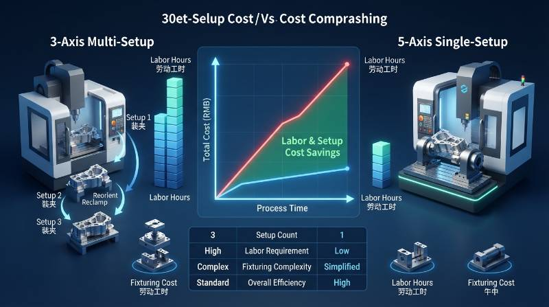
Deploying advanced 5-axis machining solutions consolidates 4 to 6 discrete 3-axis setups into a single clamping operation (done-in-one). This reduces fixturing investments and eliminates cumulative positioning errors.
| Parameter | Multi-Setup 3-Axis Machining | Consolidated 5-Axis Machining |
|---|---|---|
| Workholding Fixturing | Requires 3 to 5 custom soft jaw sets ($1,200–$2,500 NRE) | Standard pneumatic self-centering vise / dovetail ($0 NRE) |
| Operator Labor Time | High (manual re-orientation between operations) | Low (single touch-off and continuous multi-side cutting) |
| Tolerance Stack-Up | ±0.030mm to ±0.050mm cumulative error across setups | ±0.005mm true position across multiple faces |
| Part Unit Cost (Batch: 100) | Baseline Cost (100%) | 25% to 35% Total Cost Reduction |
Technical Trade-Offs & Cost Multipliers: Materials, Tolerances, and Finishes
Material selection and secondary processing significantly influence final unit pricing. Consulting a detailed CNC machining material selection guide enables engineers to balance yield strength, thermal properties, and raw machinability ratings.
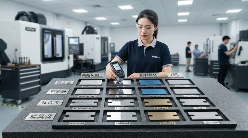
For structural applications where ultra-high yield strength is not mandatory, substituting standard aerospace alloys with high-machinability variants per ASTM international material specifications reduces spindle cycle duration by up to 50%.
| Category | Specification | Relative Machinability / Processing Cost | DFM Recommendation |
|---|---|---|---|
| Material Alloy | Aluminum 6061-T6 | 100% (Baseline – High Speed) | Optimal for general structural components. |
| Material Alloy | Aluminum 7075-T6 | 130% Cost (Higher tool wear & billet raw cost) | Restrict strictly to high-stress structural airframes. |
| Material Alloy | Stainless 304 / 316 | 250–320% Cost (Work hardening, slow speeds) | Substitute with 303 Free-Machining Stainless where permissible. |
| Surface Finish | As-Machined (Ra 3.2μm / 125 μin) | Baseline (No secondary finishing cost) | Standard for enclosed mechanical assemblies. |
| Surface Finish | Fine Machined (Ra 0.8μm / 32 μin) | +35% to +60% Spindle Cost (Micro step-overs) | Specify solely on fluid-seal dynamic faces. |
| Secondary Finish | Anodizing Type II (Sulfuric) | Standard Batch Pricing | Cost-effective corrosion resistance and coloration. |
| Secondary Finish | Anodizing Type III (Hardcoat) | +50% to +80% over Type II Anodize | Use only for extreme abrasive wear environments. |
Batch Scaling and Billet Nesting: Bridge Production Economics (50 to 5,000 Units)
CNC machining exhibits steep economies of scale through production ramp phases. Non-recurring costs—such as CAM toolpath validation, machine zeroing, and first article inspection (FAI)—are fixed costs amortized over the quantity ordered.
Amortization and Multi-Part Nesting
- Unit Volume Amortization: Moving from a 5-unit prototype batch to a 250-unit bridge production run typically reduces per-unit prices by 45% to 60%.
- Tombstone Fixturing: On horizontal machining centers (HMCs) or 5-axis trunnions, multiple components are nested from a single extruded bar or plate billet. This cuts automated tool change frequency and maximizes unattended spindle utilization.
- Raw Stock Sizing: Standardize component outer boundaries to match commercially available standard bar sizes (e.g., 50mm x 100mm stock). Ordering non-standard raw cross-sections forces pre-squaring passes, turning paid billet directly into wasted chips.
Industrial Benchmark: Cost-Optimizing Complex 5-Axis Aerospace Housings
High-complexity aerospace and robotics components represent the ultimate test of cost-focused DFM.
Engineering Scenario: Deep-Cavity Thin-Wall Housing
An aerospace customer required an avionics sensor chassis milled from Aluminum 7075-T6 with the following demanding parameters:
- Deep internal cavities measuring 65mm depth with initial corner radii of R1.5mm.
- Isolated thin peripheral walls of 0.8mm subject to harmonic vibration.
- Four critical internal bearing bores requiring ±0.005mm positioning and H6 dimensional limits.
Tyneen DFM Intervention and Results
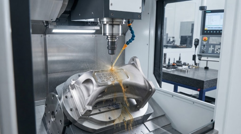
- Corner Radii Optimization: Increased internal pocket corner radii from R1.5mm to R4.0mm, allowing high-feed 6mm dynamic roughing end mills rather than fragile micro-tools. Spindle cycle time dropped by 28 minutes per unit.
- Setup Consolidation: Migrated the part from 5 separate 3-axis setups to a single continuous clamping cycle on a 5-axis DMG MORI machining center using dovetail stock preparation.
- GD&T Rationalization: Preserved the strict ±0.005mm tolerance strictly across bearing bores, while converting exterior cover fastener hole positions to ISO 2768-mK (±0.1mm).
- Economic Result: Overall manufacturing cost per part fell by 34.2% across a 300-piece batch, with zero non-conformances during final automated CMM verification.
Tyneen Manufacturing Infrastructure: Certified Precision & Quality Systems
Cost reduction is useless if dimensional accuracy is compromised. Tyneen enforces stringent manufacturing controls backed by international industry certifications.
Certified Production & Inspection Capabilities
- Quality Certifications: Fully certified manufacturing operations meeting ISO 9001:2015, IATF 16949 (Automotive), and AS9100D (Aerospace) standards.
- Advanced Multi-Axis Fleet: 3-axis, 4-axis, and simultaneous 5-axis CNC machining centers from DMG MORI and Mazak with high-pressure through-spindle cooling.
- Metrology Validation: Zeiss Coordinate Measuring Machines (CMM) with scanning tactile probes providing sub-micron resolution (down to ±0.0015mm), laser surface profilometers, and optical optical comparators.
- Engineered DFM Support: Every engineering drawing and CAD file receives automated and expert engineering review within 2 hours to uncover cost-saving geometry modifications before metal cutting begins.
3-Step Production Pathway: From DFM Optimization to Delivery
Eliminate costly manufacturing friction and streamline your production supply chain with our verified 3-step procurement process.
Accelerate Your Precision Manufacturing with Tyneen
- Step 1: CAD & Drawing Upload: Submit your 3D CAD models (STEP, IGES, Parasolid) and 2D PDF manufacturing prints specifying critical datums and GD&T requirements.
- Step 2: Automated DFM & Quoting (< 2 Hours): Receive an actionable DFM cost-reduction report alongside a competitive, transparent manufacturing quote.
- Step 3: Precision Production & CMM Inspection: Fast-turn component manufacturing on advanced multi-axis centers with comprehensive Zeiss CMM dimensional inspection reports and global express delivery.
Frequently Asked Questions About CNC Machining Cost Reduction
What is the single most effective way to reduce machining costs?
Minimizing total machine setups. Consolidating features onto faces that can be accessed in a single clamping setup—or utilizing 5-axis machining—cuts fixturing costs and manual operator labor more than adjusting raw material stock sizes.
How does internal corner radius affect milling prices?
Designing internal radii equal to or smaller than a standard tool radius causes cutting tool chatter and requires smaller diameter tools running at low feeds. Sizing corner radii 10–15% larger than standard cutter radii allows smooth, continuous, high-speed toolpaths without deceleration.
Why are tight tolerances so expensive in CNC production?
Tolerances tighter than ±0.025mm require specialized finishing tools, reduced spindle feed rates, frequent tool offset adjustments, climate-controlled environments, and 100% CMM inspection, increasing cycle times and quality overhead.
Is Aluminum 6061 always cheaper to machine than 7075?
Yes. Aluminum 6061-T6 provides longer cutting tool life, lower raw stock cost per kilogram, and faster chip evacuation rates compared to high-zinc 7075-T6 alloys.
How can I avoid expensive secondary surface finishing costs?
Specify standard as-machined surface finishes (Ra 3.2μm / 125 μin) for non-sealing surfaces. Reserve fine Ra 0.8μm finishes and specialized Type III hardcoat anodizing only for dynamic O-ring seals or extreme wear interfaces.