Aluminum 7075 Aerospace CNC Machining | Tyneen Service
Material Metallurgy & Grade Selection: 7075-T6 vs 7075-T651 vs 7075-T7351
Aluminum 7075 aerospace CNC machining transforms high-strength, zinc-alloyed wrought aluminum billets into flight-critical structural links, bulkheads, and brackets demanding ultimate tensile strengths exceeding 570 MPa. Success relies on balancing temper-dependent mechanical properties, controlling internal residual stresses, and deploying precise 5-axis subtractive milling routines.
The primary alloying element in the 7000-series family is zinc (5.1% to 6.1%), complemented by magnesium (2.1% to 2.9%) and copper (1.2% to 2.0%). This composition precipitates \(\text{MgZn}_2\) (eta phase) intermetallic compounds during artificial aging, delivering strength comparable to structural steel at one-third the volumetric density.
Selecting the proper temper grade governs part stability during and after heavy material removal. Specifying raw stock under ASTM B221 or AMS 4045 defines the boundary conditions for machinability and stress behavior:
- 7075-T6: Solution heat-treated and artificially aged. Delivers maximum yield strength (~503 MPa) but retains significant quenching stresses, leading to post-machining distortion on hog-out components.
- 7075-T651: Solution treated, stress-relieved via controlled stretching (0.5% to 3.0% permanent set), and artificially aged. This temper eliminates bulk internal quenching forces and serves as our default baseline for monolithic aircraft links.
- 7075-T7351: Overaged temper specifically engineered to mitigate Stress Corrosion Cracking (SCC) and exfoliation corrosion in sustained-load or marine flight environments, trading roughly 10-15% peak tensile strength for high fracture resistance.
When selecting aerospace-grade aluminum materials for high-stress linkages, matching the temper to the component’s primary load profile prevents structural failure caused by micro-cracking or dimensional drift.
Aerospace Alloy Benchmark: 7075-T651 vs 6061-T6, 2024-T3, and Ti-6Al-4V
Flight structural engineers must evaluate competing structural alloys based on mechanical limits, cyclic fatigue life, and CNC machinability index values.
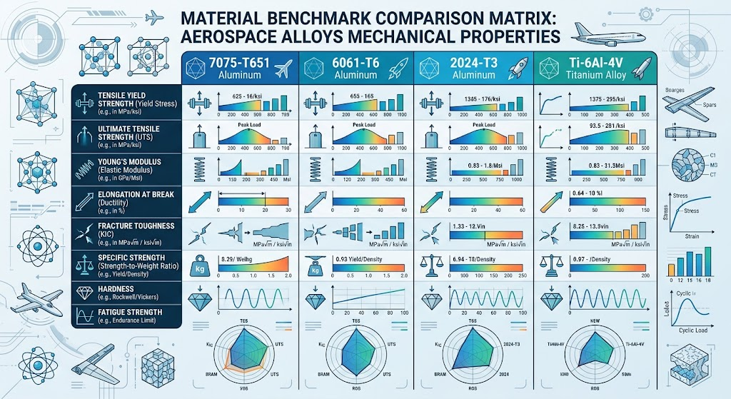
| Mechanical Property | 7075-T651 | 6061-T6 | 2024-T3 | Ti-6Al-4V (Grade 5) |
|---|---|---|---|---|
| Tensile Yield Strength (MPa) | 503 | 276 | 345 | 880 |
| Ultimate Tensile Strength (MPa) | 572 | 310 | 483 | 950 |
| Fatigue Limit (\(10^7\) cycles, MPa) | 159 | 96.5 | 138 | 510 |
| Fracture Toughness (\(K_{IC}\), \(\text{MPa}\sqrt{\text{m}}\)) | 29 | 29 | 37 | 55 |
| Density (\(\text{g/cm}^3\)) | 2.81 | 2.70 | 2.78 | 4.43 |
| Relative Machinability Index (%) | 80% (Base Reference) | 100% (High Speed) | 75% (Abrasive) | 22% (Difficult) |
7075-T651 yields an 82% higher yield strength over 6061-T6, making it the superior selection for primary load links where weight reduction is paramount.
Managing Residual Stress: The Tyneen AeroStress Mitigation Protocol™
Machining complex, thin-webbed 7075 structural components unlocks internal thermal and metallurgical stresses. Without disciplined process controls, asymmetric stress distribution causes geometric bowing and out-of-tolerance twists post-unclamping.
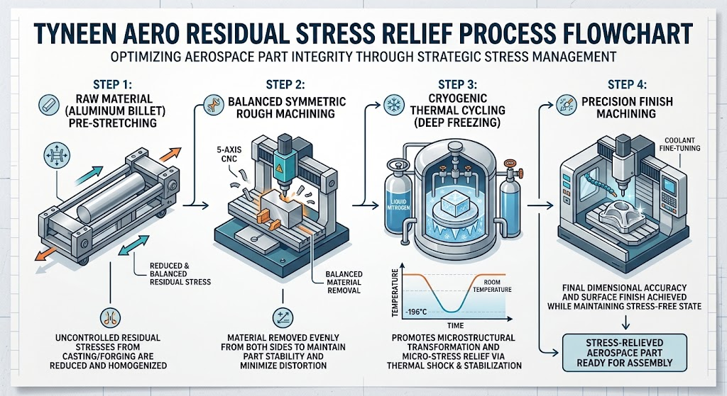
We solve volumetric distortion by deploying our proprietary Tyneen AeroStress Mitigation Protocol™, structured across four manufacturing stages:
- Stage 1: Verified Pre-Stretched Stock Selection: Raw materials must comply with AMS-QQ-A-200/11 or SAE International AMS specifications with ultrasonic testing per AMS-STD-2154 Class A to verify the absence of metallurgical voids and localized stress clusters.
- Stage 2: Equalized Symmetrical Roughing: Material removal is sequenced in balanced, alternate-side pockets, leaving a uniform 1.0 mm envelope on all functional surfaces. Removing metal evenly prevents core stress vectors from acting unidirectionally.
- Stage 3: Sub-Critical Thermal & Cryogenic Stabilization: Semi-machined parts undergo controlled thermal stabilization cycling from -73°C up to +155°C. This artificial relaxation cycle redistributes localized lattice shear stresses without compromising core T651 temper hardness.
- Stage 4: Light-Load High-Speed Finishing: Final finishing cuts operate at tool engagements not exceeding 0.15 mm radial depth of cut (\(a_e\)), preventing new mechanical or thermal stresses from entering the surface boundary layer.
Engineering Insight: In our manufacturing experience across thin-walled wing link components, switching from single-setup hog-out roughing to our 4-stage stabilization protocol reduced free-state part distortion from 0.42 mm down to under 0.03 mm across 600 mm overall part lengths.
DFM Guidelines for Deep Pockets and Thin-Wall Aerospace Ribs
Weight reduction in aerospace structural links requires deep pockets bounded by high-aspect-ratio ribs. Without optimized Design for Manufacturability (DFM) parameters, tool deflection and harmonic chatter can damage surface integrity and blow out critical tolerances.
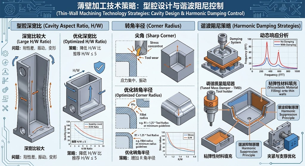
When preparing CAD models for aerospace CNC milling services, we recommend adhering to these geometric design boundaries:
- Minimum Wall Thickness: Maintain unsupported rib thickness at or above 0.8 mm for depths under 25 mm. For rib depths exceeding 50 mm, taper walls by 1° to 2° or step thickness up to 1.5 mm minimum.
- Pocket Depth-to-Width Ratios: Keep cavity depth-to-cutter-diameter under 5:1 whenever possible. Ratios reaching 8:1 require specialized dynamic trochoidal clearing routines with neck-reduced carbide endmills to avoid harmonic chatter.
- Internal Corner Radii: Specify inside vertical fillet radii at least 15% to 20% larger than the milling tool radius (e.g., use an \(R = 3.8\,\text{mm}\) corner fillet for a 6 mm end mill). This prevents instantaneous tool engagement spikes at corner transitions.
- Floor-to-Wall Fillets: Incorporate transitional bottom blend fillets of \(R \ge 1.5\,\text{mm}\) to disperse peak stress concentrations during aerodynamic and mechanical loading.
Adhering to these geometric thresholds avoids custom vibration-damped tooling and eliminates unnecessary cycle time penalties.
High-Precision 5-Axis Toolpaths & High-Speed Milling Strategies
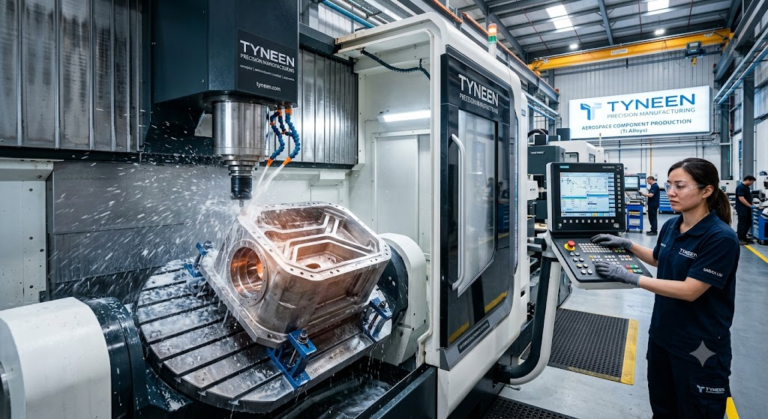
Machining complex structural links from monolithic 7075-T651 billets requires modern 5-axis CNC machining centers equipped with dynamic 20,000+ RPM spindles and digital motion control architectures.
Executing continuous 5-axis advanced machining toolpaths maintains optimal tool orientation, minimizing overhang length and maximizing dynamic tool assembly rigidity.
| Operation Type | Cutter Type & Coating | Cutting Speed (\(V_c\), m/min) | Feed per Tooth (\(f_z\), mm/z) | Coolant Delivery |
|---|---|---|---|---|
| Dynamic Trochoidal Roughing | 3-Flute Solid Carbide (Uncoated / ZrN) | 450 – 750 | 0.12 – 0.22 | High-Pressure TSC (70 bar) |
| Thin-Rib Semi-Finishing | 2-Flute Variable Helix Solid Carbide | 500 – 850 | 0.08 – 0.14 | Through-Spindle Flood + Blast |
| Surface & Fillet 5-Axis Finish | 3-Flute Mirror Polished Ball Nose / Bull | 600 – 1000 | 0.04 – 0.08 | Filtered Mist / Soluble Oil |
High-Pressure Through-Spindle Coolant (TSC) operating at \(\ge 70\,\text{bar}\) (1000 PSI) evacuates chips from deep cavities, preventing recutting and localized work hardening.
Surface Finishing & Pre-Machining Dimensional Tolerancing
High-stress 7075 aluminum aircraft parts require specialized surface treatments to withstand galvanic corrosion, environmental oxidation, and cyclic fatigue. CAM programming must account for the dimensional adjustments introduced by chemical and electrochemical finishing.
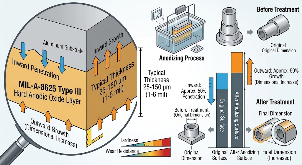
Pre-machining dimensional planning depends on the post-processing specification:
- MIL-A-8625 Type III Hardcoat Anodizing: Typically specified at 0.0020 in (50 µm) total thickness. The coating penetrates 50% into the substrate and builds up 50% on the surface. Machinists must adjust nominal feature dimensions by 0.0010 in (25 µm) per surface (0.0020 in on diametrical bores).
- MIL-DTL-5541 Type II Chemical Conversion (Chromate): Produces a microscopically thin passivation layer (< 0.00005 in / 1.2 µm) with zero meaningful dimensional growth, requiring no pre-machining dimensional compensation.
- Aerospace Controlled Shot Peening (AMS 2430 / SAE AMS-S-13165): Introduces compressive residual stresses on finished link radii, extending cyclic fatigue life by retarding surface micro-crack initiation.
Precise coordination between CNC programming offsets and NADCAP-accredited chemical processing avoids out-of-spec pin bores and bearing journals during final assembly.
Flight-Critical Aerospace Applications for Machined 7075 Components
Because of its strength-to-density ratio and fatigue resistance, 7075-T651/T7351 is the preferred alloy for critical structural load-path components across commercial, defense, and space platforms:
- Main Wing Spar Caps & Internal Rib Links: High-moment structural members experiencing sustained tension-compression cycles during aerodynamic flight maneuvers.
- Fuselage Bulkhead Structural Fittings: High-stress interconnect brackets distributing aerodynamic and internal pressurization loads into the airframe skeleton.
- Landing Gear Actuation Links & Bellcranks: Flight mechanisms demanding extreme yield strength and impact resistance during high-velocity touchdown loads.
- Missile Guidance Airframe Fins & Rocket Stage Separation Brackets: Aerodynamic control surfaces where mass reduction directly expands payload velocity and range.
- Satellite Structural Payload Adaptors: Rigid, weight-optimized frames designed to survive high-g static and acoustic launch environments.
Quality Assurance: AS9100D, AS9102 FAI, CMM, and NDT Inspections
Aerospace manufacturing demands complete process traceability and rigorous inspection protocols. Every critical dimension must be verified against original model-based definition (MBD) engineering datasets.
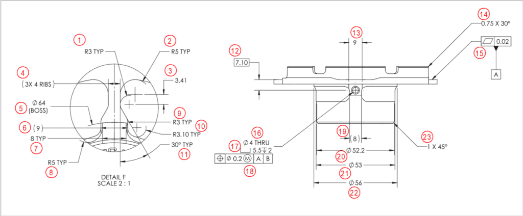
Quality management systems operating under AS9100 Rev D and ISO 9001:2015 rely on multi-tier inspection procedures:
- AS9102 First Article Inspection (FAI): Generation of Form 1 (Part Number Accountability), Form 2 (Product Process Accountability), and Form 3 (Characteristic Accountability) documenting every ballooned drawing dimension.
- Multi-Axis Coordinate Measuring Machine (CMM) Verification: Automated touch-probe and laser scanning in climate-controlled quality laboratories (20°C ± 0.5°C) to verify geometric dimensioning and tolerancing (GD&T) down to ±0.005 mm.
- Non-Destructive Testing (NDT): Fluorescent Penetrant Inspection (FPI per ASTM E1417) to detect surface defects and micro-fissures, alongside Ultrasonic Testing per ASTM B594 for subsurface voids.
- Material Traceability: Complete retention of Certified Mill Test Reports (CMTR / MTC), guaranteeing chemical composition compliance and mechanical lot certification.
Frequently Asked Questions (FAQ) About 7075 Aerospace CNC Machining
Is Aluminum 7075 weldable for aerospace structural applications?
Standard fusion welding (such as TIG/MIG) is generally not recommended for Aluminum 7075. High zinc and copper content promotes severe micro-segregation, hot cracking, and porosity in the heat-affected zone (HAZ), reducing joint strength by over 50%. Aerospace structural links are mechanically fastened or joined using solid-state Friction Stir Welding (FSW).
When should I specify 7075-T7351 instead of 7075-T651?
Specify 7075-T7351 when the component is subjected to sustained transverse tensile stresses in corrosive environments (such as marine operations or naval aviation). The T7351 overaged temper significantly boosts resistance to Stress Corrosion Cracking (SCC) while sacrificing roughly 10% of peak yield strength.
How do internal radii affect machining cycle times for deep pockets?
Specifying tight inside corner radii (\(R < 2\,\text{mm}\)) relative to pocket depth forces machinists to use smaller-diameter, extended-reach end mills. This requires reduced feed rates to manage tool deflection and chatter, driving up machine cycle times by 35% to 60%. Increasing corner radii lowers production costs.
What are standard lead times for custom aerospace 7075 CNC links?
Standard production lead times range from 3 to 5 weeks, encompassing raw billet acquisition with full MTC traceability, roughing, intermediate stress relief, 5-axis finishing, surface passivation, and AS9102 FAI documentation. Expedited rapid prototyping options can deliver components in 7 to 10 business days.