PEEK CNC Milling for High-Voltage Insulators | Tyneen
Engineering PEEK for Critical High-Voltage Insulation Systems
Precision PEEK CNC milling delivers high-voltage electrical insulators capable of withstanding electric fields exceeding 19 kV/mm without dielectric breakdown. By combining high glass transition temperatures (143°C) with low moisture absorption (<0.1%), polyetheretherketone maintains electrical volume resistivity and mechanical rigidity under extreme operating gradients.
Traditional thermoset insulators and ceramics often crack under severe thermal shock or mechanical vibration. Machined PEEK components provide an impact-resistant, lightweight alternative for aerospace power distribution, subsea penetrators, and high-voltage substation switchgear.
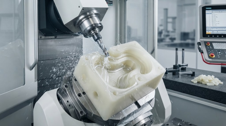
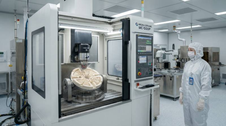
Executing high-tolerance dielectric geometry requires tailored cutting mechanics. Utilizing precision CNC milling services prevents localized thermal degradation and micro-void formation that degrade isolation ratings.
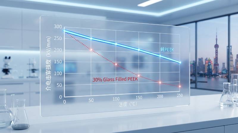
Dielectric & Thermal Benchmarks: Virgin PEEK vs. Filled Grades
Material formulation dictates dielectric performance under sustained high-voltage stress. While glass or ceramic reinforcements boost tensile modulus, they introduce microscopic dielectric boundary interfaces.
Virgin unfilled PEEK (such as Victrex 450G or Ketron 1000) provides the highest volume resistivity and Comparative Tracking Index (CTI). Glass-filled variants (PEEK-GF30) offer higher stiffness for structural bushings, but internal glass fiber interfaces can initiate tracking paths if subjected to continuous partial discharge.
Dielectric Strength Definition: The maximum electrical field an insulating material can withstand intrinsically without experiencing electrical breakdown and becoming conductive, standardized under ASTM D149 testing protocols.
Our machining trials and material validations through advanced engineering plastics machining benchmarks yield the comparative electrical properties below.
| Property Standard | Virgin PEEK (Unfilled) | PEEK-GF30 (30% Glass) | Carbon-Filled PEEK |
|---|---|---|---|
| Dielectric Strength (ASTM D149, 1mm) | 23.0 kV/mm | 17.5 kV/mm | Electrically Conductive (N/A) |
| Comparative Tracking Index (IEC 60112) | CTI 150 – 175 V (PLC 3) | CTI 125 – 150 V (PLC 4) | < 100 V (Unusable for HV) |
| Volume Resistivity (ASTM D257) | ≥ 1016 Ω·cm | ≥ 1015 Ω·cm | 102 – 106 Ω·cm |
| Dielectric Constant (1 MHz, IEC 60250) | 3.2 | 3.5 | N/A |
| Continuous Service Temp (°C) | 240°C – 260°C | 260°C – 280°C | 260°C |
Electrical Creepage, Flashover, and Surface Roughness (Ra) Dynamics
In high-voltage design, the shortest distance along an insulator surface between two conductive paths defines the creepage distance. Sub-optimal CNC tool paths generate microscopic cusps, valleys, and feed-line grooves that compromise this boundary.
Micro-grooves aligned parallel to electrical field gradients act as physical channels for electron avalanche propagation. When local electrical fields concentrate at micro-peaks, partial discharges ionize surrounding air, accelerating flashover events along the surface.
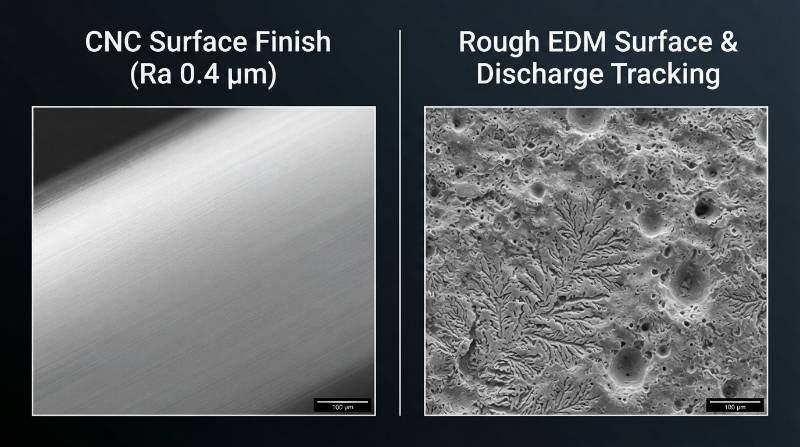
Suppressing Corona Discharge via Micro-Finishing
Controlling surface finish directly elevates flashover inception voltage. Standard commercial turning leaves finishes between Ra 1.6 – 3.2 µm, which can induce micro-arcs at operating voltages above 10 kV.
- Target Micro-Finish: Maintaining surface roughness Ra ≤ 0.4 µm eliminates micro-cusp field emission spikes.
- Perpendicular Toolpath Orientation: Programming tool passes perpendicular to the electrical field increases the effective tracking barrier.
- Zero-Burr Transition Radii: Micro-deburring shed tips to minimum R 0.2 mm removes razor edges that act as corona initiation points.
The Tyneen Dielectric-Safe Machining Protocol™ (DSMP)
High-voltage insulators demand strict contamination control. Standard water-soluble coolants leave conductive ionic surfactant residues in micro-fissures, reducing surface tracking resistance according to IEC 60112 standards.
To eliminate dielectric degradation, we developed The Tyneen Dielectric-Safe Machining Protocol™ (DSMP), an operational framework applied across all precision insulator production lines.
- Stock Purity Verification: Incoming extruded PEEK billets undergo ultrasonic non-destructive testing to verify zero internal extrusion voids, porosity, or carbon inclusions.
- Vortex-Chilled Dry Milling: We eliminate wet cutting fluids entirely. Multi-jet sub-zero chilled air (-10°C) maintains cutter temperatures below PEEK’s glass transition threshold, evacuating chips without ionic residue.
- Multi-Stage DI Ultrasonic Extraction: Finished parts undergo multi-stage cavitation cleaning in 18 MΩ·cm deionized water heated to 65°C, removing microscopic particulate and static-bound debris.
- Vacuum Desiccation & Cleanroom Packaging: Components undergo vacuum baking at 120°C for 4 hours to drive off absorbed ambient moisture, followed by sealed antistatic Class 10,000 packaging.

Precision 5-Axis Milling Strategies for Convoluted Sheds and Ribs
High-voltage standoff insulators feature convoluted sheds (skirts) that maximize creepage distance within compact dimensional envelopes. These geometries require deep undercut milling with high aspect ratios.
Single-axis plunge cuts generate excessive radial cutting forces, deflecting thin shed walls (often <1.5 mm thickness). This deflection leads to chatter marks, thermal glazing, and wall thickness variations.

Toolpath Optimization & Tooling Dynamics
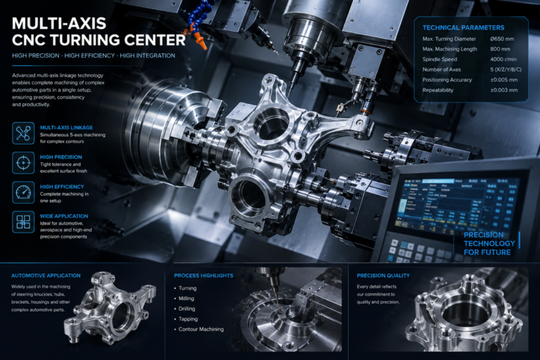
By leveraging multi-axis advanced machining solutions, our engineers apply continuous simultaneous 5-axis toolpaths that maintain optimal tool engagement angles on compound shed curves.
- Polycrystalline Diamond (PCD) Tooling: PCD end mills with mirror-polished flutes prevent material smearing and deliver stable edge sharpness over long production runs.
- High Positive Rake Geometries: 15°–18° positive rake angles shear PEEK cleanly, reducing cutting forces and preventing deformation on thin ribs.
- Vibration-Damping Custom Fixturing: Internal expanding mandrels support thin-walled hollow cores, suppressing harmonic vibration across high-RPM spindle passes.
Stress-Relief Annealing Cycles for Sub-Micron Dimensional Stability
Extruded PEEK stock contains significant residual extrusion stresses. Machining removes outer layers, unbalancing internal stresses and triggering geometric warping over time.
In high-voltage switchgear bushings with critical threaded interfaces, post-machining movement can cause micro-gaps, leading to corona discharge. Controlled thermal annealing relieves internal stress, stabilizes crystalline structure, and ensures pitch accuracy.
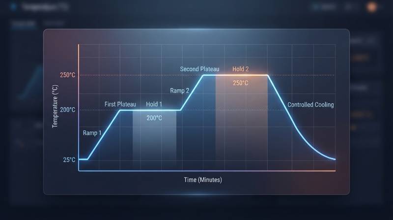
| Annealing Stage | Target Temperature | Ramp Rate / Dwell Time | Process Objective |
|---|---|---|---|
| 1. Pre-Machining Heat Soak | 160°C | 10°C / hour; Hold 4 hours | Relieves bulk extrusion stress prior to roughing |
| 2. Intermediate Crystalline Normalization | 200°C – 250°C | Hold 1 hr per 6mm wall thickness | Applied after semi-finishing to equalize internal stresses |
| 3. Controlled Cool-Down | Ambient Room Temp | Cool at ≤ 10°C / hour | Prevents thermal shock and anisotropic shrinkage |
Critical High-Voltage Application Scenarios
PEEK insulators operate in demanding environments where failure results in major downtime or critical system damage. Below are key applications engineered across our multi-axis milling facilities.
SF6-Free Switchgear Bushings & Vacuum Feedthroughs
With global power distribution shifting away from potent greenhouse gases like SF6, new alternative gas-insulated switchgear runs at higher field concentrations. Precision-machined PEEK bushings deliver the required dielectric margins while maintaining airtight hermetic o-ring sealing under constant pressure cycles.
Aerospace & High-Altitude Power Modules
At high altitudes, Paschen’s Law dictates that breakdown voltage drops significantly due to reduced atmospheric pressure. Milled PEEK standoffs engineered with convoluted shed profiles preserve the creepage distance necessary to suppress corona discharge across lightweight avionics packages.
Quality Verification: CMM Inspection & Dielectric Assurance
Guaranteeing insulator reliability requires rigorous verification combining physical metrology and non-destructive electrical testing.
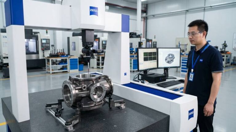
- Coordinate Measuring Machine (CMM) Verification: Multi-sensor Zeiss CMMs inspect undercut contours, pitch runout, and thin shed concentricity within sub-micron tolerances (±0.003 mm).
- 3D Optical Surface Profilometry: Non-contact white-light interferometry scans surface textures to ensure zero tool chatter or micro-cusps above Ra 0.4 µm.
- Partial Discharge Testing: Per IEC 60270 standards, completed components can be subjected to high-voltage AC stress screening to verify partial discharge levels remain <5 pC at specified working voltages.
Before launching high-voltage production runs, engineers can directly request a precision machining quote for manufacturability reviews and custom dielectric component development.
Frequently Asked Questions (FAQs)
Why is Virgin PEEK preferred over Glass-Filled PEEK for high-voltage standoffs?
Virgin PEEK contains no structural filler interfaces, providing homogeneous volume resistivity (≥ 1016 Ω·cm) and superior dielectric strength (23 kV/mm). Glass fibers in reinforced grades can create microscopic dielectric boundary mismatches, increasing the risk of internal tracking paths under sustained electrical stress.
Can standard CNC flood coolants be used when milling PEEK insulators?
No. Water-soluble flood coolants contain ionic compounds, biocides, and surfactants that penetrate microscopic surface fissures in PEEK. These ionic residues permanently compromise surface tracking resistance (CTI). We mill high-voltage PEEK dry using vortex-cooled compressed air.
What machining tolerances can be achieved on complex PEEK insulator sheds?
With multi-stage stress-relief annealing and 5-axis continuous milling, tolerances of ±0.005 mm (±0.0002 in) are routinely maintained on diameters and pitch features, with surface finishes reaching Ra 0.2 – 0.4 µm without manual polishing.
Is post-machining annealing always required for PEEK insulators?
For high-voltage components with asymmetrical geometry, deep undercut sheds, or precision threads, intermediate and post-machining annealing is critical. It relieves internal stresses, preventing dimensional creep and out-of-round distortion that cause air voids and partial discharge during high-voltage assembly.
Need High-Reliability PEEK Electrical Insulators?
From 5-axis thin-shed milling to zero-ionic dry machining protocols, Tyneen manufactures mission-critical dielectric components tailored to your exact high-voltage specifications.