Hybrid Manufacturing: 3D Printing & CNC Milling Guide
The Hybrid Evaluation Matrix: Balancing Geometric Freedom with Micron GD&T
Hybrid manufacturing merges metal additive manufacturing (AM) with subtractive CNC machining to eliminate the limitations of both individual disciplines. Direct Metal Laser Sintering (DMLS) constructs intricate internal channels and organic lattices, but raw builds typically yield rough surface finishes of Ra 6.3–12.5 μm and dimensional accuracy limited to ±0.1–0.3 mm.
Integrating precision CNC milling services bridges this gap by machining functional interfaces down to ±0.005 mm with mirror-like surface roughness below Ra 0.4 μm.

Engineering teams must evaluate components through a structured technical framework before selecting hybrid routing over conventional billet machining or casting:
- Internal Geometries: Presence of fluid paths, cooling circuits, or lattices inaccessible to endmills.
- Buy-to-Fly Ratio: High-cost superalloys where solid billet hogging wastes over 80% of raw stock.
- Datum Transfer Repeatability: Features requiring absolute location precision relative to internal printed channels.
- Metallurgical Density: Mission-critical components requiring pore-free microstructure per ASTM F3001 standards.
Sequential vs Single-Setup Hybrid Architectures
Hybrid workflows follow one of two technical architectures: single-setup Directed Energy Deposition (DED) hybrid centers, or sequential routing from dedicated Powder Bed Fusion (PBF/DMLS) printers to multi-axis CNC machines.
While single-setup DED machines excel at hardfacing and volumetric component repair, sequential DMLS-to-CNC workflows deliver superior powder consolidation, sub-30 μm layer resolution, and scalable throughput for complex structural production.
The Tyneen Closed-Loop Datum & Stress-Relief Protocol (CLD-SRP)
“The primary challenge in subtractive post-processing of additive preforms is datum degradation caused by residual stress release and unpredictable thermal shrinkage.”
Tyneen resolves dynamic part distortion using a proprietary 4-stage engineering protocol that locks datum references across both manufacturing phases:
- Phase 1: Integrated Sacrificial Datum Lugs: CAD models incorporate sacrificial precision-ground tooling tabs. These features serve as zero-point clamping references on the CNC bed before secondary removal.
- Phase 2: Stress-Relief Vacuum Annealing: Additive blanks undergo controlled thermal cycles while still attached to the build plate. This neutralizes directional thermal gradients and prevents warping during wire EDM separation.
- Phase 3: Dynamic Renishaw Probing: Multi-axis CNC centers use high-precision tactile touch probes to map the actual volumetric profile of the near-net blank, automatically updating the Work Coordinate System (WCS) to center stock across critical surfaces.
- Phase 4: Adaptive High-Speed Finishing: Toolpaths account for variable stock depth, deploying constant-engagement trochoidal cutting cycles that eliminate tool deflection.
Metallurgical Integrity and Post-Processing: HIP, Heat Treatment & Machinability
Additive superalloys exhibit anisotropic microstructures and residual micro-porosity (typically 0.1–0.5% void volume) that degrade fatigue life if left unaddressed. To achieve full structural integrity in high-performance aerospace materials, preforms must undergo Hot Isostatic Pressing (HIP).
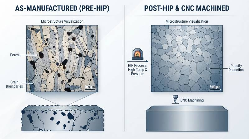
HIP cycles applied at 920°C and 100 MPa argon pressure for Titanium Ti-6Al-4V consolidate internal voids to 99.9% theoretical density. This treatment aligns material properties with forging equivalents per ISO/ASTM 52900 standards.
Machining additive superalloys requires tailored cutting tool strategies:
- Titanium Ti-6Al-4V (Grade 5/23): Demands aggressive coolant delivery (70+ bar through-spindle) to counter low thermal conductivity and suppress chip adhesion.
- Inconel 718: Post-HIP precipitation hardening increases hardness above 40 HRC, requiring AlTiN-coated micro-grain carbide or whisker-reinforced ceramic inserts with positive rake geometry to prevent work hardening.
- AlSi10Mg Aluminum: Fast laser solidification yields silicon networks that cause abrasive micro-chipping on cutting edges, requiring polished PCD (polycrystalline diamond) tooling.
Extreme Niche Benchmark: 5-Axis Finishing of Topologically Optimized Aerospace Valve Bodies
A recent flight-critical aerospace project required a 50% mass reduction on a Titanium Ti-6Al-4V hydraulic valve manifold operating at 350 bar working pressure. Solid billet machining was unfeasible due to 12 intersecting internal fluid passages requiring non-linear paths.
Tyneen engineered a sequential hybrid production run leveraging advanced 5-axis machining to overcome tight geometric limits:
- Additive Preform: DMLS printing produced the organic shell, weight-reducing external pockets, and internal smooth-radius conformal hydraulic circuits without cross-drilled sealing plugs.
- Thermal Conditioning: Parts underwent vacuum stress relief at 650°C for 3 hours, followed by HIP at 920°C/100 MPa, eliminating micro-voids and residual stress.
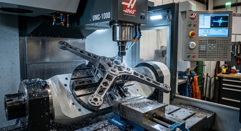
- 5-Axis Precision Post-Machining: Using dynamic probing and multi-axis DMG MORI centers, Tyneen milled 8 critical valve spool bores to ±0.005 mm true position and diametrical tolerance.
- Hydraulic Sealing Interfaces: O-ring groove gland faces were micro-finished to Ra 0.4 μm to guarantee bubble-tight containment under cyclic 500 bar proof pressure.
The hybrid solution cut raw material consumption by 74%, reduced total component weight by 48%, and eliminated 6 failure-prone leak paths associated with conventional cross-drilled manifold plugs.
Substantiating Economics & Quality: Hybrid AM+CNC vs Billet Machining vs Casting
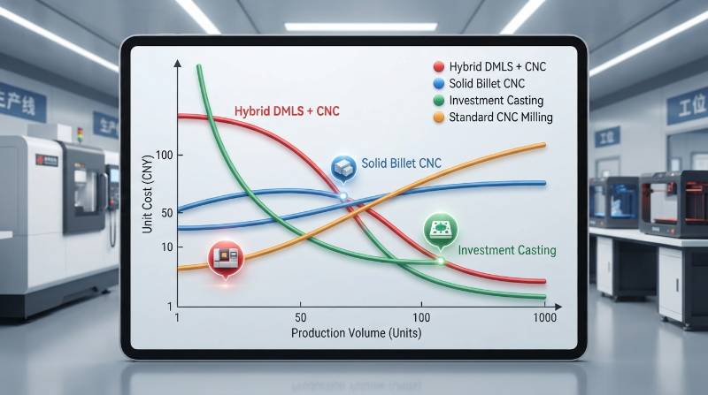
Evaluating total unit cost between hybrid manufacturing, solid billet cutting, and investment casting requires assessing tooling amortizations, cycle times, and raw superalloy scrap loss.
When combined with complementary precision CNC turning solutions for rotational features, hybrid processing delivers a clear economic break-even against solid billet hogging for geometries with buy-to-fly ratios exceeding 5:1.
Comparative Cost-Volume Breakdown Table
| Evaluation Parameter | Pure 5-Axis Billet CNC | Investment Casting + CNC | Hybrid DMLS + 5-Axis CNC (Tyneen) |
|---|---|---|---|
| Buy-to-Fly Ratio | 14:1 to 18:1 | 2.5:1 to 3.5:1 | 1.2:1 to 1.5:1 |
| Tooling / NRE Costs | $1,500 – $4,000 (Fixturing) | $25,000 – $60,000 (Hard Tooling) | $500 – $1,200 (Soft/Modular Jigs) |
| Prototype Lead Time | 3 to 5 Weeks | 14 to 24 Weeks | 4 to 8 Days |
| Internal Flow Channel Freedom | Severe (Straight-line only) | Moderate (Core pull constraints) | Infinite (Conformal 3D curves) |
| Machining Spindle Time | 100% (Full bulk hogging) | 25% (Semi-finish + Finish) | 15% (Critical surface finishing only) |
Metrology & NDT Verification: Zeiss CMM and CT Scanning
Verifying hybrid components requires dual-layer metrology: high-resolution Non-Destructive Testing (NDT) for additive interiors, alongside contact metrology for precision machined interfaces.
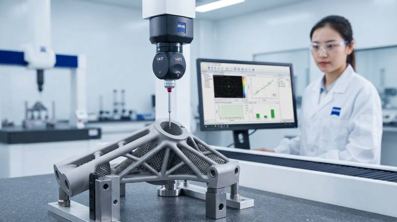
Tyneen inspects every hybrid production batch using industrial Computed Tomography (CT) scanning to verify internal channel clearance and locate subsurface inclusions. Subtractive features are inspected on climate-controlled Zeiss CMM systems capable of sub-micron measurement uncertainty, backed by complete EN 10204 3.1 Material Test Reports (MTR).
Tyneen Certified Hybrid Infrastructure: Single-Source AS9100D & DMG MORI Fleet
Splitting additive printing and CNC machining between disparate vendors introduces handoff errors, mismatched datum schemes, and untraceable quality liabilities. Tyneen operates as a single-source manufacturing partner providing unified engineering control.
- Machining Fleet: High-precision 3, 4, and 5-axis DMG MORI and Mazak machining centers equipped with Renishaw high-speed probing systems.
- Certified Quality Systems: Production workflows fully certified to AS9100D (Aerospace), ISO 9001:2015, and IATF 16949 (Automotive).
- In-House Thermal Post-Processing: Vacuum furnace stress relief, solution heat treatment, and validated HIP partner networks.
- Rapid DFM Engineering: Direct-to-engineer technical design analysis delivered in under 2 hours.
3-Step Implementation Pathway: From Additive DFM to Finished Flight-Ready Parts
Streamlined Engineering Action Pathway
- Upload 3D CAD & Print/Machining Prints: Submit native STEP models accompanied by 2D GD&T drawings specifying critical bore tolerances, thread callouts, and sealing surface finishes.
- Receive Comprehensive DFM & Quote in 2 Hours: Tyneen additive and CNC engineers optimize your build orientation, define sacrificial datum locations, and calculate exact stock allowances.
- First Article Validation & Rapid Production: Full production setup, vacuum stress relief, 5-axis CNC finishing, and Zeiss CMM inspection with fast global delivery.
Frequently Asked Questions (FAQ)
What machining allowances should be designed into 3D printed blanks?
Standard engineering practice allocates 0.8 mm to 1.5 mm of stock allowance on surfaces designated for subtractive finishing. This provides sufficient depth of cut to drop below the rough as-printed surface layer and reach base material density without overburdening cutting tools.
How does hybrid manufacturing prevent cutting tool failure on Inconel and Titanium?
By producing blanks to near-net shape, hybrid manufacturing eliminates heavy roughing and pocketing operations where tool wear and thermal shock are most severe. Cutting tools only perform light semi-finishing and finishing passes, reducing tooling expenditures and cycle time.
Is hybrid manufacturing cost-effective for production runs above 100 units?
Yes, specifically for topologically optimized structures with internal channels or parts made from high-cost alloys like Inconel 718 or Ti-6Al-4V. In these scenarios, the savings in raw stock waste and elimination of hard casting tooling make hybrid production economically competitive well beyond 500 units.