GD&T in CNC Machining: The Precision Tolerance Guide
The Engineering Framework for GD&T in Multi-Axis CNC Manufacturing
Geometric Dimensioning and Tolerancing (GD&T) is a symbolic engineering language defined by standards such as ASME Y14.5-2018 and ISO 1101. It explicitly communicates the allowable variation of geometric features rather than relying solely on linear distance boundaries.
GD&T Definition: A standardized system of symbols, rules, and mathematical definitions used on technical drawings to specify the theoretical nominal geometry of parts and the permissible variation across size, location, orientation, and form.
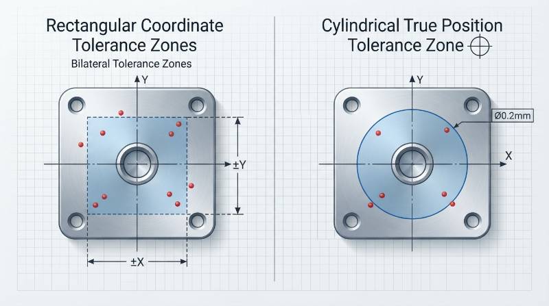
Legacy linear plus-minus tolerancing (±0.05 mm) creates restrictive square or rectangular tolerance boundaries. This traditional method often rejects functional components while permitting out-of-square assemblies to slip through production lines.
Modern multi-axis CNC machining operates across four geometric classifications:
- Form: Flatness, straightness, circularity, and cylindricity independent of external references.
- Orientation: Perpendicularity, parallelism, and angularity relative to datum features.
- Location: True position, concentricity, and symmetry tied to a datum reference frame.
- Profile: Surface and line profiles controlling complex freeform contours.
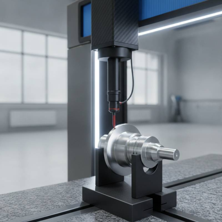
Executing tight GD&T requires synchronization across CAD modeling, CAM kinematic toolpaths, workpiece workholding, and coordinate measuring machine (CMM) tactile probe paths.
Anatomy of a Feature Control Frame and Datum Precedence
The Feature Control Frame (FCF) acts as the operational instruction set for CNC machinists and quality control inspectors. It dictates the geometric constraint, the tolerance boundary geometry, material condition modifiers, and the datum hierarchy.
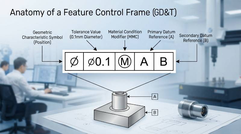
Compartment Breakdown of the Feature Control Frame
- Geometric Characteristic Symbol: Defines the geometric control (e.g., Position, Profile of a Surface, Perpendicularity).
- Tolerance Zone Descriptor: Specifies the shape and magnitude (e.g., ⌀0.025 mm denotes a cylindrical zone of 0.025 mm diameter).
- Material Condition Modifiers: Indicates Maximum Material Condition (Ⓜ), Least Material Condition (Ⓛ), or Regardless of Feature Size (RFS, default).
- Datum Reference Frame (Primary, Secondary, Tertiary): Establishes the spatial coordinate system that arrests the part’s 6 Degrees of Freedom (DOF).
The 3-2-1 Locating Principle in CNC Workholding
A Datum Reference Frame (DRF) must physically align with CNC fixture locating pins, jaws, and ground tooling plates:
- Primary Datum (3 Points): Constrains 3 degrees of freedom (1 translation, 2 rotations), defining the primary plane.
- Secondary Datum (2 Points): Constrains 2 degrees of freedom (1 translation, 1 rotation), establishing the alignment axis.
- Tertiary Datum (1 Point): Constrains the final translational degree of freedom, setting the coordinate origin.
The 14 Core GD&T Symbols: Characteristics and CNC Process Realities
In high-precision manufacturing, applying the correct geometric controls prevents tolerance accumulation and ensures flawless mechanical assembly. Below is the full classification of all 14 GD&T symbols applied in precision CNC milling services and turned components.
| Family | Symbol & Characteristic | Datum Needed? | Tolerance Zone Type | Typical CNC Machining Method | Tyneen Precision Window |
|---|---|---|---|---|---|
| Form | Straightness (—) | No | 2 parallel lines / cylinder | Precision grinding, dynamic turning | ±0.003 mm |
| Flatness (⏥) | No | 2 parallel planes | Face milling with fly-cutter, lapping | 0.005 mm | |
| Circularity (○) | No | 2 concentric circles | CNC boring, precision turning | 0.004 mm | |
| Cylindricity (⌭) | No | 2 coaxial cylinders | Multi-pass cylindrical grinding | 0.006 mm | |
| Orientation | Perpendicularity (⊥) | Yes | 2 parallel planes at 90° | 5-axis single-setup end milling | 0.005 mm |
| Parallelism (∥) | Yes | 2 parallel planes / lines | Dual-side straddle milling, grinding | 0.005 mm | |
| Angularity (∠) | Yes | 2 parallel planes at basic angle | 5-axis simultaneous rotary positioning | 0.008 mm | |
| Location | True Position (⨁) | Yes | Cylindrical or planar zone | High-speed peck drilling, boring bars | ⌀0.008 mm (MMC) |
| Concentricity (◎) | Yes | Cylinder centered on datum | Live-tooled CNC turning, dual-spindle | 0.008 mm | |
| Symmetry (⌯) | Yes | 2 parallel planes about center | Precision slotting, balanced milling | 0.010 mm | |
| Profile | Profile of a Surface (⌓) | Yes / Optional | 3D bilateral or unilateral offset | 5-axis 3D ball-nose surface machining | 0.012 mm |
| Profile of a Line (⌒) | Yes / Optional | 2 parallel boundary curves | High-feed contour milling | 0.010 mm | |
| Runout | Circular Runout (↗) | Yes | 2 coaxial circles per cross-section | High-precision turning centers | 0.005 mm |
| Total Runout (⇗) | Yes | 2 coaxial cylinders over full length | Swiss-type turning, OD grinding | 0.006 mm |
The Tyneen 4D Kinematic Datum & Tolerance Verification Protocol
To eliminate discrepancies between CAD design models and finished parts, Tyneen deploys the proprietary Tyneen 4D Kinematic Datum Protocol. This systematic methodology integrates CAD, CAM, multi-axis machining, and metrology validation.
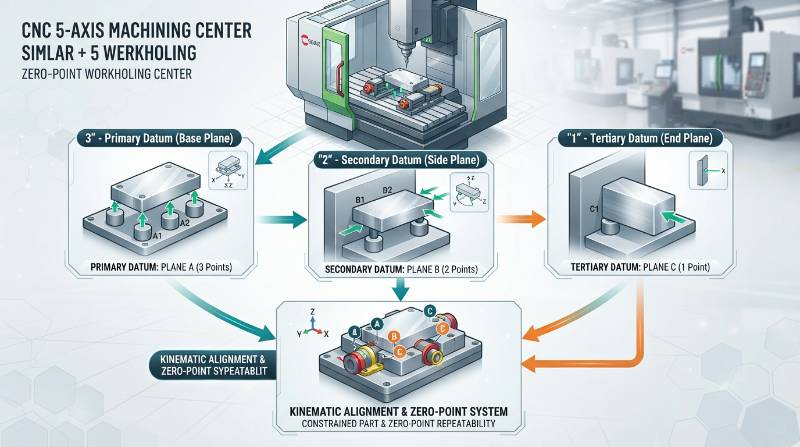
- CAD/CAM Datum Kinematic Synchronization: The physical workpiece fixture zero on our 5-axis advanced machining capabilities is aligned directly with the drawing’s Primary Datum [A], Secondary [B], and Tertiary [C] surfaces. This eliminates secondary coordinate transformation errors.
- In-Process Multi-Axis Deflection & Thermal Compensation: Our machine controllers dynamically correct for cutter tool deflection and linear thermal growth (holding ambient machine shop temperatures at 20°C ±1°C).
- Bonus Tolerance & Modifier Optimization: Algorithmic tool offset adjustments actively optimize hole-making tools toward the Maximum Material Condition baseline, unlocking bonus tolerance reserves.
- Sub-Micron Zeiss 3D CMM Coordinate Verification: Final physical inspection matches the exact mathematical datum simulator sequence established in the engineering drawing.
Material Condition Modifiers: Unlocking MMC Bonus Tolerances and Cost Savings
Material Condition Modifiers establish how a geometric tolerance dynamically adapts based on the actual produced size of a Feature of Size (FOS), such as a bore, pin, boss, or slot.
The Three Core Modifiers
- Maximum Material Condition (MMC – Ⓜ): The state where the feature contains the maximum amount of material within its dimensional limits (smallest hole diameter, largest pin diameter).
- Least Material Condition (LMC – Ⓛ): The state where the feature contains the minimum amount of material (largest hole diameter, smallest pin diameter). Used for wall-thickness critical retention.
- Regardless of Feature Size (RFS): The default condition under ASME Y14.5-2018 where the geometric tolerance remains strictly static regardless of the feature’s actual manufactured size.
The Mechanics of Bonus Tolerance
When an internal hole is specified at MMC, any departure from the minimum hole size toward the maximum allowable size adds directly to the true position tolerance window as “bonus tolerance.”
Bonus Tolerance = Actual Produced Hole Diameter – Minimum Permissible Hole Diameter (MMC)
Example: Hole ⌀10.00 (+0.10/-0.00 mm), True Position ⌀0.05 mm Ⓜ. If produced at ⌀10.08 mm: Total Tolerance = 0.05 + (10.08 – 10.00) = ⌀0.13 mm.
Specifying MMC on clearance bolt holes and alignment dowel patterns increases the functional tolerance zone by 20% to 57%. This prevents unnecessary part rejections caused by rigid, legacy coordinate boundaries.
True Position vs. Coordinate Plus-Minus Tolerancing: Machining Impact
When a technical drawing specifies hole centers using linear coordinates like X = 50.00 ±0.05 mm and Y = 50.00 ±0.05 mm, it creates a square tolerance boundary with an area of 0.010 mm² (0.10 mm × 0.10 mm).
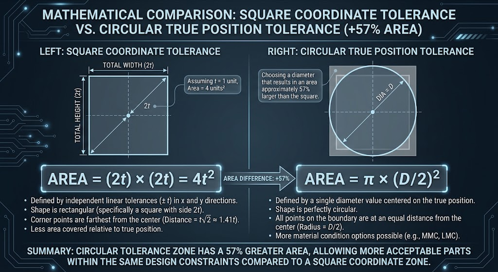
True position converts this boundary into a cylindrical tolerance zone with a diameter equal to the diagonal of the square: ⌀ = √(0.10² + 0.10²) ≈ ⌀0.1414 mm.
Tolerance Area Increase = [(0.0157 – 0.0100) / 0.0100] × 100% = +57.08%
True Position provides 57% more allowable tolerance area while maintaining the exact same radial clearance required for mating fasteners. In CNC turning and multi-tasking, this extra window allows machinists to maintain tool life without violating functional assembly requirements.
High-Precision Benchmark: 5-Axis Aerospace Turbine & Medical Block Verification
To demonstrate GD&T execution in mission-critical applications, consider a complex titanium hydraulic valve block produced by Tyneen for aerospace flight control systems.
| Critical Feature | GD&T Specification | Material & Setup | Machining Challenge | Achieved CMM Result |
|---|---|---|---|---|
| Cross-Port Bores (×12) | ⨁ ⌀0.010 mm Ⓜ | A | B | C | | Ti-6Al-4V Grade 5, DMG MORI 5-Axis | Deep-hole tool wander and thermal expansion | ⌀0.0058 mm (100% Pass) |
| Sealing Mounting Face | ⏥ 0.006 mm | A | | Hydraulic Zero-Point Clamping | Stress-relief part warpage after roughing | 0.0034 mm |
| Organic Fluid Gallery | ⌓ 0.015 mm | A | B | C | | Solid carbide micro ball end mill | Cusp height variation and continuous multi-axis toolpath | 0.0082 mm |
| Spool Valve Guide Shaft | ⇗ 0.008 mm | A-B | | Dual-spindle turn-mill with cryogenic coolant | Chucking runout and workpiece deflection | 0.0041 mm |
Selecting appropriate high-performance CNC materials like titanium alloys and 316L stainless steel requires dedicated multi-stage stress relief thermal cycles to prevent post-machining geometric relaxation.
CMM Metrology, Probe Path Planning, and AS9102 FAIR Verification
Verifying micron-level GD&T callouts requires high-precision coordinate measuring machines operating within temperature-controlled cleanroom environments.
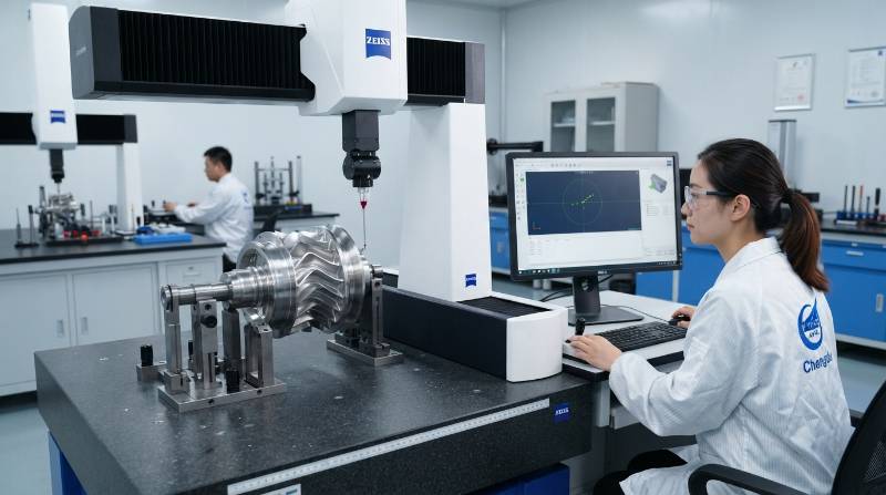
CMM Measurement Fundamentals
- Stylus Tip Calibration & Sphere Compensation: Ruby and silicon nitride probe styli calibrated against UKAS/NIST-traceable master spheres to eliminate vector deflection.
- Environmental Normalization: Metrology suites maintained strictly at 20°C (±0.5°C) with 45% relative humidity to match ISO 1 standards.
- Mathematical Fitting Algorithms: Utilizing Gaussian Least Squares (LSQ) for general statistical fitting and Chebyshev Minimum Zone (MZ) for functional clearance boundaries.
Every critical batch includes an AS9102 Rev B First Article Inspection Report (FAIR), detailing complete balloon drawings, nominal GD&T specs, measured values, and tool calibration certificates.
Technical Comparisons & Verification: ASME Y14.5 vs. ISO 1101 and Drawing Pitfalls
Engineering teams working across North American and European supply chains must account for core differences between ASME and ISO standard frameworks.
| Core Principle / Symbol | ASME Y14.5-2018 (United States) | ISO 1101 / ISO GPS (International) |
|---|---|---|
| Rule #1 (Envelope Principle) | Default: Size limits automatically control form (perfect form at MMC). | Not Default: Independency Principle applies unless the Ⓔ symbol is specified. |
| Default Material Condition | RFS is implied unless Ⓜ or Ⓛ is present. | RFS is implied unless Ⓜ or Ⓛ is present. |
| Concentricity & Symmetry | Eliminated in the 2018 revision; replaced by Position and Profile. | Retained as active, valid symbols. |
| Basic Dimension Indicator | Boxed dimension: [ 50.00 ] | Boxed dimension: [ 50.00 ] (Theoretically Exact Dimension – TED) |
Common GD&T Drafting Errors to Avoid
- Missing Datum References in Location Controls: Specifying True Position without referencing a Secondary or Tertiary datum, leaving rotation unconstrained.
- Over-Constraining Form Beyond Machine Limits: Demanding Flatness 0.001 mm across a 600 mm thin-walled aluminum plate where residual stresses cause dynamic flexing.
- Omitting Basic Dimensions: Using position or profile callouts without defining theoretical basic dimensions back to the DRF.
Tyneen Metrology Infrastructure: Zeiss CMM Validation & Quality Accreditations
Manufacturing ultra-precision components with comprehensive GD&T compliance requires strict quality control systems and modern inspection equipment.
- Certifications: ISO 9001:2015, IATF 16949 (Automotive), and AS9100D (Aerospace) certified production facilities.
- Metrology Suite: Zeiss PRISMO and ACCURA 3D CMMs providing length measurement errors as low as E₀ = 0.9 + L/350 μm.
- Multi-Axis Fleet: 3-axis, 4-axis, and 5-axis DMG MORI and Hermle CNC machining centers with direct linear glass scales.
- In-House Expertise: Level II certified GD&T metrology engineers performing comprehensive Design for Manufacturability (DFM) reviews.
Streamlined 3-Step Pathway: From GD&T Drawing to Certified CNC Parts
Tyneen provides a structured workflow to transition complex technical drawings into verified, high-precision metal and polymer components:
The Tyneen Production Action Pathway
- Step 1: Upload CAD & GD&T Drawings – Submit 3D CAD models (STEP, IGES) alongside 2D GD&T drawings (PDF, DWG) via our encrypted portal.
- Step 2: Automated DFM & Tolerance Analysis – Receive a comprehensive DFM feasibility review, datum alignment check, and quote within 2 hours.
- Step 3: Precision Multi-Axis Production & AS9102 FAIR – Fast-turn CNC production backed by 100% Zeiss CMM GD&T inspection and international dispatch.
Frequently Asked Questions About GD&T in CNC Machining
What is the most cost-effective way to specify hole locations in CNC milling?
The most economical approach is applying True Position with Maximum Material Condition (MMC – Ⓜ) referenced to a clearly defined Datum Reference Frame (e.g., | ⨁ | ⌀0.10 Ⓜ | A | B | C |). This unlocks bonus tolerance as the hole diameter approaches the maximum limit, increasing usable production windows and extending cutting tool lifespan.
How does Tyneen verify Profile of a Surface on complex 3D freeform contours?
Tyneen uses continuous tactile scanning on Zeiss 3D CMMs alongside non-contact laser surface scanners. The measured point cloud is aligned to the CAD model via a CAD-to-part mathematical best fit, generating a color-coded 3D deviation deviation map that quantifies spatial conformance within the specified bilateral or unilateral tolerance zone.
Why does MMC save machining costs compared to Regardless of Feature Size (RFS)?
RFS requires maintaining the exact same positional tolerance regardless of the actual hole size. MMC allows the positional tolerance to grow larger when the hole is machined above its minimum diameter. This dynamic expansion reduces scrap rates, eases tool wear sensitivity, and lowers quality inspection bottlenecks.
How do thermal fluctuations affect CMM GD&T measurements?
Materials like aluminum expand at roughly 23 μm/m/°C, while titanium expands at 8.6 μm/m/°C. Even a 3°C temperature variation can cause a 100 mm aluminum part to drift by 7 μm, which can consume an entire tolerance band. Tyneen conducts all CMM metrology in cleanrooms stabilized at 20°C (±0.5°C) to maintain complete measurement accuracy.
Partner with Tyneen for Precision GD&T Manufacturing
Do you have components with complex feature control frames, tight true position callouts, or demanding surface profiles? Request an engineering DFM consultation with Tyneen today and receive a detailed tolerance review and quote in under 2 hours.