GD&T in Precision Machining: ASME Y14.5 Engineering Guide
GD&T in Precision Machining: The ASME Y14.5 Engineering Foundation
Geometric Dimensioning and Tolerancing (GD&T) is an international symbolic language used on engineering drawings to explicitly define the allowable variation of geometric features. Governed globally by standards such as ASME Y14.5-2018 and ISO 1101:2017, GD&T moves beyond linear dimensions to control form, orientation, profile, and location based on actual functional interfaces.
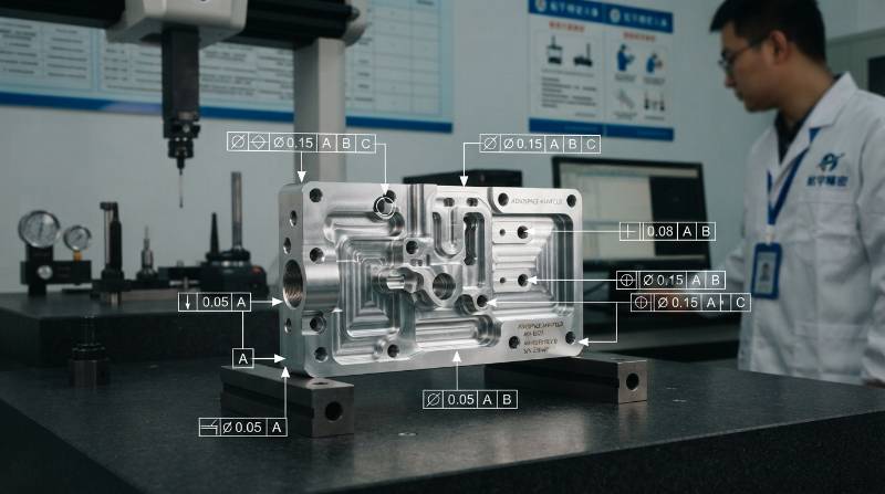
In high-precision CNC manufacturing, GD&T establishes a clear mathematical relationship between design intent, physical workholding, and multi-axis toolpaths. Traditional coordinate tolerancing (± tolerances) creates ambiguous, non-functional rectangular zones that cause unnecessary scrap, rejected parts, and assembly failures. GD&T defines clear, cylindrical, or surface-based tolerance zones relative to a defined Datum Reference Frame (DRF), guaranteeing proper fit and function across mission-critical assemblies.
The 4-Pillar GD&T Machinability & Precision Evaluation Framework
Before initiating toolpath generation or raw material prep, Tyneen evaluates 2D technical drawings against a rigorous 4-pillar Design for Manufacturability (DFM) framework. This process ensures design requirements align with shop-floor kinematic realities and metrology constraints.
- Pillar 1: Datum Scheme Machinability & Fixture Alignment: Verifies that specified datums represent rigid, functional, and accessible physical surfaces. Ensures the theoretical 3-2-1 Datum Reference Frame directly aligns with zero-point hydraulic or mechanical CNC workholding.
- Pillar 2: Material Condition & Dynamic Bonus Tolerance Economics: Identifies where Maximum Material Condition (MMC) or Least Material Condition (LMC) can be applied to feature control frames. This provides shop-floor bonus tolerances that lower manufacturing costs without compromising fit.
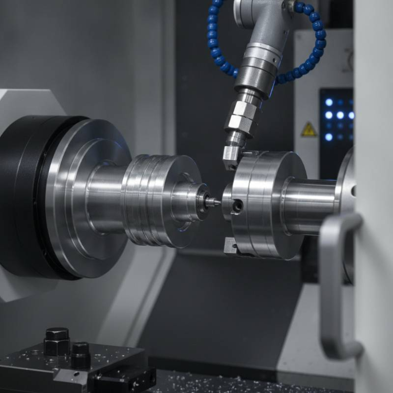
- Pillar 3: Multi-Axis Process Feasibility: Matches geometric tolerances directly to CNC kinematic capabilities across advanced CNC machining solutions, Swiss-type turning, Wire EDM, and sub-micron jig grinding.
- Pillar 4: Metrology Traceability & CMM Probe Accessibility: Validates that all toleranced surfaces are inspectable via tactile scanning probes, optical sensors, or custom air gaging without introducing gauge-deflection errors.
Fundamentals of GD&T: Symbol Classifications, Rules, and Feature Control Frames
Modern GD&T under ASME Y14.5 organizes geometric controls into five distinct categories. Each controls a specific physical attribute relative to, or independent of, reference datums.
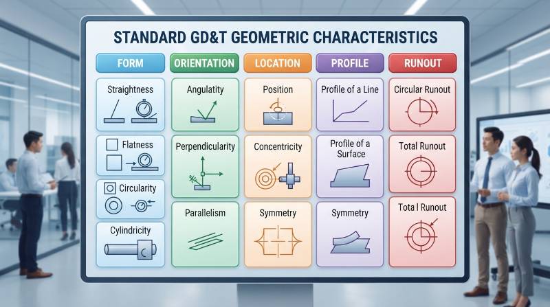
| Category | Characteristic Symbol | Datum Required? | Primary CNC Manufacturing Control |
|---|---|---|---|
| Form | Flatness, Straightness, Circularity, Cylindricity | No | Tool deflection, machine-way straightness, clamping distortion |
| Orientation | Perpendicularity, Parallelism, Angularity | Yes | Axis squareness, rotary table indexing accuracy, spindle trueness |
| Location | True Position | Yes (Typically) | Linear drive resolution, thermal drift, zero-point offset tracking |
| Profile | Profile of a Surface, Profile of a Line | Optional / Yes | Simultaneous 5-axis continuous interpolation, ball-nose cusp height |
| Runout | Circular Runout, Total Runout | Yes | Spindle bearing runout, chuck concentricity, tailstock alignment |
Fundamental GD&T Rule 1 (Envelope Principle): ASME Y14.5 mandates that the surface or surfaces of a regular feature of size cannot extend beyond its boundary of perfect form at Maximum Material Condition (MMC). If a machined shaft is produced at its maximum allowable diameter, it must be perfectly straight and round.
Standard Revision Note: The ASME Y14.5-2018 revision officially eliminated Concentricity and Symmetry due to measurement ambiguity, high inspection costs, and frequent misapplication. Industry practice now achieves these alignments via True Position (for centerlines/axes) or Profile of a Surface.
Feature Control Frames (FCF) and the 3-2-1 Datum Reference Frame (DRF)
The Feature Control Frame is the core rectangular structure that conveys geometric requirements. It reads sequentially from left to right: Geometric Characteristic Symbol, Tolerance Zone Shape & Value, Material Condition Modifiers, and Datum Precedence (Primary, Secondary, Tertiary).
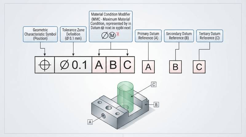
A part is fully oriented in three-dimensional space using the 3-2-1 Datum Reference Frame rule. This locks all 6 degrees of freedom (3 translational along X, Y, Z, and 3 rotational around u, v, w):
- Primary Datum (A): Minimum 3 contact points. Constrains 3 degrees of freedom (1 translation, 2 rotations).
- Secondary Datum (B): Minimum 2 contact points perpendicular to A. Constrains 2 degrees of freedom (1 translation, 1 rotation).
- Tertiary Datum (C): Minimum 1 contact point perpendicular to both A and B. Constrains the final translational degree of freedom.
Material Condition Modifiers: MMC, LMC, and Bonus Tolerance Calculations
Material condition modifiers alter the stated geometric tolerance depending on the actual manufactured size of the feature:
- Maximum Material Condition (MMC, Ⓜ): The state where the feature contains the maximum amount of material within its dimensional limits (e.g., smallest hole diameter, largest pin diameter).
- Least Material Condition (LMC, Ⓛ): The state where the feature contains the minimum amount of material (e.g., largest hole diameter, smallest pin diameter). Used to preserve minimum wall thickness.
- Regardless of Feature Size (RFS): The default state under ASME Y14.5. The geometric tolerance remains fixed regardless of produced feature size.
When MMC is applied to a Feature Control Frame, CNC machinists gain bonus tolerance as the feature departs from its MMC size toward LMC:
Total Allowable Positional Tolerance = Stated Base Tolerance + Bonus Tolerance
Example Calculation: Consider an internal bore specified as ⌀10.00 mm (+0.05 / -0.00 mm) with a True Position of ⌀0.02 mm Ⓜ relative to Datums A|B|C. MMC is ⌀10.00 mm. If the bore is machined to ⌀10.04 mm:
- Bonus Tolerance = 10.04 mm – 10.00 mm = 0.04 mm
- Total Allowable True Position = ⌀0.02 mm (base) + 0.04 mm (bonus) = ⌀0.06 mm
This 200% increase in allowable positional tolerance saves usable parts without compromising mating assembly clearances.
GD&T vs Traditional Plus-Minus Tolerancing: Eliminating Stack-Up & Scrap
Traditional coordinate dimensioning specifies independent ± limits for X and Y coordinates. This creates a square or rectangular tolerance zone. However, round fasteners, dowel pins, and shafts mate radially, requiring a circular tolerance boundary.
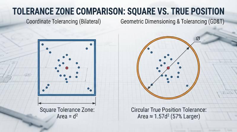
For a coordinate tolerance of ±0.05 mm, the resulting square zone measures 0.10 × 0.10 mm, yielding an allowable area of 0.010 mm². The maximum permissible shift occurs across the square’s diagonal:
A cylindrical True Position zone with a diameter equal to this functional diagonal (⌀0.1414 mm) yields a total usable area of 0.0157 mm².
(0.0157 – 0.010) / 0.010 × 100% = 57% Tolerance Expansion.
By switching to GD&T True Position, engineering gains a 57% larger manufacturing window at no cost, completely eliminating diagonal assembly interference failures caused by square tolerance assumptions.
DFM Cost-Curve Correlation: True Position Tightness vs Machining Economics
Manufacturing costs increase non-linearly as True Position tolerances drop below standard commercial machining limits. Tight positional tolerances require specialized workholding, reduced feed rates, extra semi-finishing passes, active thermal compensation, and dedicated CMM inspection routines.
| True Position Zone (⌀) | Required CNC Operations | Tooling & Setup Strategy | Cost Factor Multiplier |
|---|---|---|---|
| ⌀0.20 mm – ⌀0.30 mm | Standard spot-drill & twist drill / rough endmill | Standard vise, standard ER collet chucks | 1.0× (Baseline) |
| ⌀0.05 mm – ⌀0.10 mm | Carbide drill, high-speed endmill finishing | Hydraulic/shrink-fit holders, 3-axis CNC | 1.4× – 1.8× |
| ⌀0.015 mm – ⌀0.03 mm | Rough bore, fine finish boring bar or reaming | Single-setup precision 5-axis CNC milling services, probing | 2.5× – 3.5× |
| ≤ ⌀0.005 mm | Jig grinding, high-precision Wire EDM, lapping | Climate-controlled cell (±0.5°C), hydrostatic ways | 5.0× – 8.0×+ |
To control production budgets, apply tight true position callouts (≤ ⌀0.03 mm) only to dowel pin locations, bearing pockets, and critical sealing surfaces. Non-locating clearance holes should remain at ⌀0.15 mm to ⌀0.25 mm.
Machine-Tool Kinematics: Bridging CAD Datums to Multi-Axis CNC Fixturing
Translating theoretical 3D CAD datums into stable machine coordinates requires strict kinematic planning. Whenever a part is removed and reclamped across multiple fixtures, stacked error occurs (typically 0.015 mm to 0.040 mm per setup change).
To maintain sub-micron geometric integrity, Tyneen executes complex GD&T drawing requirements by pairing multi-axis simultaneous operations with zero-point tooling. Using single-setup multi-sided machining on 5-axis machining centers or high-rigidity multi-axis mill-turn centers with high-precision CNC turning capabilities preserves datum relationships without secondary setups.
The Tyneen Datum-to-Spindle Alignment Protocol (DSAP)
Tyneen uses a proprietary four-step closed-loop machining protocol to synchronize physical workpieces with programmed ASME Y14.5 datum schemes:
- Virtual Kinematic Simulation: CAM programmers map CAD datums directly into machine space, calculating volumetric error maps and tool-vector approaches to prevent tool deflection.
- In-Process Renishaw Probing: Multi-axis touch probes automatically locate physical primary, secondary, and tertiary datums on the raw stock or pre-machined surfaces.
- Tilted Working Plane (TWP / G68.2) Offset Adjustment: The CNC controller calculates part tilt and translation, transforming coordinate systems dynamically without physical shimming.
- Dynamic Thermal Compensation: Continuous thermal feedback loops monitor spindle temperature and machine-way expansion, adjusting real-time tool position to preserve orientation tolerances within 0.003 mm across long production runs.
Process Feasibility Matrix: Matching GD&T Controls to Machining Capabilities
Different manufacturing processes provide varying control over specific geometric properties. Selecting the right machining method depends heavily on part material and required tolerances. For detailed alloy selection and thermal expansion properties, consult our precision engineering materials guide.
| Machining Technology | Flatness / Straightness | Perpendicularity | True Position (⌀) | Circular / Total Runout | Surface Finish (Ra) |
|---|---|---|---|---|---|
| 5-Axis Simultaneous Milling | 0.005 mm | 0.005 mm | ⌀0.010 mm | 0.008 mm | 0.4 μm – 0.8 μm |
| Swiss-Type CNC Turning | 0.003 mm | 0.004 mm | ⌀0.008 mm | 0.002 mm | 0.2 μm – 0.4 μm |
| Precision Wire EDM | 0.002 mm | 0.002 mm | ⌀0.004 mm | N/A | 0.1 μm – 0.2 μm |
| CNC Surface / Jig Grinding | 0.001 mm | 0.002 mm | ⌀0.003 mm | 0.001 mm | 0.05 μm – 0.1 μm |
Metrology & Verification: Tactile CMM, Optical Scanning, and Air Gaging
A GD&T callout is only as valid as the metrology system used to verify it. Modern quality control labs utilize three primary verification methods:
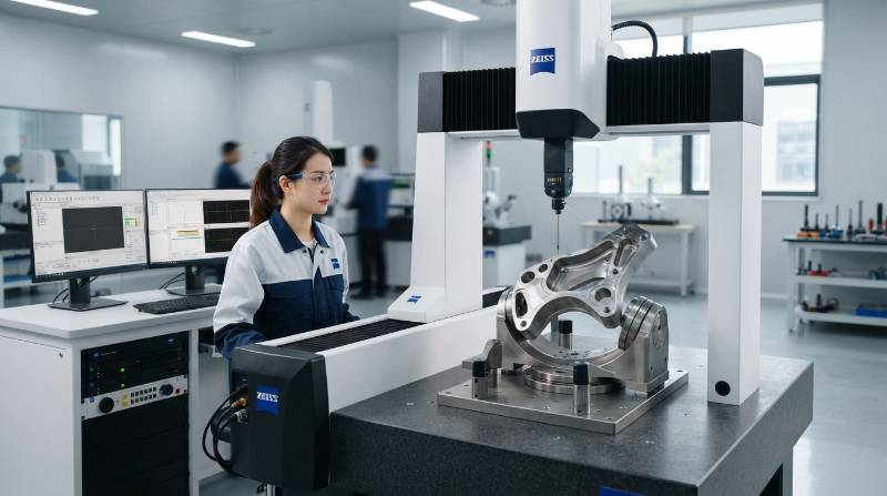
- Tactile Scanning Coordinate Measuring Machines (CMM): Continuous tactile probing (e.g., Zeiss VAST active scanning) collects thousands of discrete surface data points. This accurately measures Profile of a Surface, Flatness, and True Position without mathematical point-aliasing errors.
- High-Resolution Optical & Laser 3D Scanners: Non-contact structured light scanning captures full-field point clouds of complex, freeform surfaces. Ideal for verifying complex profiles against original CAD nominals.
- Pneumatic Air Gaging: Used on high-volume production lines for cylindrical features requiring sub-micron resolution (≤ 0.001 mm). Measures high-precision internal bores, runout, and circularity via balanced pneumatic backpressure.
AS9102 First Article Inspection (FAI) and Metrology Quality Reporting
For aerospace, medical, and defense contracts, every GD&T Feature Control Frame is assigned a unique balloon identifier on the engineering drawing. Quality engineers map these features into AS9102 Form 3 characteristic accountings.
Metrology software constructs mathematical datum simulators aligned with ASME Y14.5. This calculates actual true position deviation, records dynamic bonus tolerance, and tracks process capability metrics (Cp, Cpk ≥ 1.67) across batch production.
Technical Verification & Trade-off Comparisons: GD&T in Practice
Engineering teams often evaluate trade-offs when selecting geometric tolerances, inspection techniques, and callout strategies during product development.
| Engineering Decision | Option A | Option B | Recommended Engineering Selection |
|---|---|---|---|
| Shaft Centerline Control | Concentricity (ASME Legacy) | True Position / Total Runout | True Position / Runout: Concentricity is obsolete in Y14.5-2018. Runout controls balance and coaxiality faster at lower inspection cost. |
| Freeform Surface Control | Coordinate ± Dimensions | Profile of a Surface (All-Around) | Profile of a Surface: Coordinate tolerances cannot control 3D complex curvature, resulting in uneven steps and mismatch. |
| Production Quality Verification | Physical Functional Go/No-Go Gages | Multi-Axis CMM Point Cloud Scanning | Hybrid Approach: Physical hard gages for fast 100% shop-floor MMC checks; CMM for periodic statistical trend verification. |
Extreme Niche Engineering: 5-Axis Machining for Tight-Tolerance Aerospace Valve Housings
To highlight the practical application of GD&T, consider an extreme aerospace manufacturing scenario: a thin-walled hydraulic flight-control valve manifold machined from solid Ti-6Al-4V Grade 5 titanium.
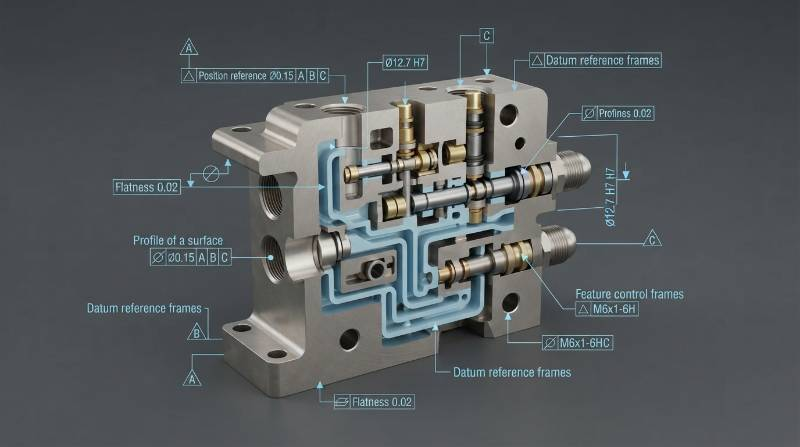
Design Constraints:
- 12 intersecting cross-bores requiring True Position within ⌀0.010 mm at MMC relative to Datum Triplet A|B|C.
- Main spool bore requires Perpendicularity within 0.005 mm relative to the primary mounting face (Datum A).
- Internal bore surface roughness requires Ra 0.4 μm straight off the machine, without manual post-polishing that could distort circularity.
- Wall thicknesses down to 0.75 mm, making the alloy prone to clamping deflection and machining chatter.
The Tyneen Manufacturing Solution:
- Machine Platform: 5-axis simultaneous machining center (DMG MORI monoBLOCK) equipped with a 20,000 RPM chilled dynamic spindle and 80-bar high-pressure through-spindle coolant.
- Fixturing: Custom vacuum zero-point fixture gripping non-functional external lugs, eliminating compressive wall distortion.
- Machining Sequence: Roughing followed by a thermal dwell cycle to allow stress relief. Finish-boring completed using custom-ground micro-adjustable polycrystalline diamond (PCD) boring tools.
- Metrology Validation: Zeiss Accura bridge CMM using a 0.5 mm ruby stylus. Measured True Position across all 12 ports held between ⌀0.004 mm and ⌀0.007 mm, delivering 100% first-pass yield and zero scrap.
Tyneen Metrology Infrastructure & Certified ASME Y14.5 Compliance
Tyneen supports precision manufacturing programs across aerospace, medical, defense, and industrial robotics with certified quality and metrology infrastructure.
- Quality Accreditations: Fully certified to ISO 9001:2015, AS9100D (Aerospace), and IATF 16949 (Automotive).
- Climate-Controlled Metrology Laboratory: Temperature stabilized to 20°C ±0.5°C with 45% relative humidity control, eliminating thermal measurement drift.
- Inspection Equipment: Sub-micron Zeiss Prismo and Accura CMMs with CALYPSO metrology software, equipped with VAST tactile scanning, optical line sensors, and rotary tables (volumetric length measurement error down to E₀ = 0.9 + L/350 μm).
- In-Line Production Metrology: Renishaw OMP60 optical transmission touch probes and high-precision laser tool setters integrated across every 3-, 4-, and 5-axis CNC machining center.
Frequently Asked Questions (FAQ) on GD&T in CNC Machining
What are the primary differences between ASME Y14.5 and ISO 1101 standards?
ASME Y14.5 defaults to Rule #1 (The Envelope Principle), meaning size tolerances automatically control form unless otherwise stated. ISO 1101 defaults to the Independency Principle, where size and form variations are independent unless an explicit envelope symbol Ⓔ is specified. ASME also eliminated concentricity and symmetry, whereas ISO retains both controls.
Why did ASME Y14.5-2018 remove the Concentricity symbol?
Concentricity evaluated whether the derived median points of diametrically opposed features aligned with a datum axis. This measurement was complex, prone to misinterpretation, and required point-cloud mapping of median points rather than surface boundaries. In precision manufacturing, functional coaxial alignment is controlled more accurately and cost-effectively using True Position or Total Runout.
How is bonus tolerance calculated on threaded tapped holes?
Unless an engineering drawing explicitly states otherwise, the Feature Control Frame on a tapped hole applies strictly to the Pitch Diameter regardless of feature size (RFS). If an MMC modifier Ⓜ is specified, bonus tolerance is derived from the pitch diameter’s departure from its minimum limit, not the minor tap drill diameter.
How do machinists maintain tight GD&T flatness on stress-prone materials?
Materials like Al 6061-T6, austenitic stainless steels (316L), and titanium alloys contain residual manufacturing stresses. Machinists maintain tight flatness tolerances (≤ 0.01 mm) by performing rough machining, releasing clamping pressure for stress equalization (or sub-zero cryogenic / oven stress-relieving), and completing final finishing passes with balanced depth-of-cut.
Executing GD&T Precision: Tyneen’s 3-Step Production Pathway
Converting complex GD&T drawing specifications into finished, inspected components follows a clear, efficient workflow:
Tyneen Precision Onboarding Pathway
- Step 1: Secure Data Transfer
Upload your native 3D CAD models (STEP, IGES) alongside 2D technical GD&T balloon drawings (PDF, DWG) via our encrypted portal. - Step 2: Automated DFM & Engineering Quote in <2 Hours
Our senior manufacturing specialists audit your datum schemes, verify tolerance stack-up risks, identify bonus tolerance opportunities, and deliver an optimized quote with clear DFM feedback. - Step 3: Multi-Axis CNC Production & AS9102 CMM Verification
Parts are machined in single-setup 5-axis workholding, verified inside our climate-controlled Zeiss CMM laboratory, and shipped with complete CMM inspection reports, material certifications, and FAI documentation.