Top 10 Design Mistakes to Avoid in Precision CNC Machining
Precision CNC machining operates under strict laws of cutting mechanics, thermodynamics, and machine kinematics. While modern 3D CAD modeling environments permit any conceivable geometry, cutting tools remain rotating cylinders that deflect under cutting forces and generate heat.
Overlooking basic Design for Manufacturability (DFM) rules transforms an elegant 3D solid model into an expensive, scrap-prone manufacturing run. Minor geometry oversights cause excessive tool chatter, rapid insert wear, broken taps, and out-of-spec geometric dimensioning.
This technical guide dissects the top design mistakes encountered in precision manufacturing. By understanding these mechanical failure modes, design teams can optimize part geometry, stabilize dimensional repeatability, and reduce unit costs.
The 5-Pillar Precision Machinability Framework: Evaluating CAD Models Beyond Geometry
To systematically identify design risks before releasing production drawings, manufacturing engineers evaluate CAD geometry against physical machining dynamics. Evaluating a part solely on visual fit neglects the physical stresses of chip formation.
Tyneen applies a 5-pillar evaluation framework during initial automated DFM reviews to assess how physical cutting loads impact production feasibility:
- Tool Reach & Deflection Dynamics: Analysis of cutter overhang ratios (L/D) and cantilever beam bending stresses.
- Tolerance-to-Capability Index: Verification that specified limits match machine repeatability without requiring excessive manual burnishing or high scrap rates.
- Clamping & Fixture Accumulation: Calculating raw stock reference surfaces, chuck grip pressures, and datum shift across multiple setups.
- Material Removal Mechanics: Evaluating chip evacuation channels, cutter engagement angles, and specific cutting energy requirements.
- Post-Finishing Growth Stack-Ups: Calculating chemical plating build-ups and surface treatment thickness shifts relative to final functional dimensions.
δ: End mill tip deflection (mm), F: Radial cutting force (N), L: Tool overhang length (mm), E: Tool material Young’s modulus (GPa), I: Area moment of inertia (I = π × D⁴ / 64) (mm⁴)
Because cutter deflection scales with the cube of tool overhang length (L³), doubling tool stickout increases deflection by a factor of eight. This physical reality governs corner radii, wall height limits, and cavity depths.
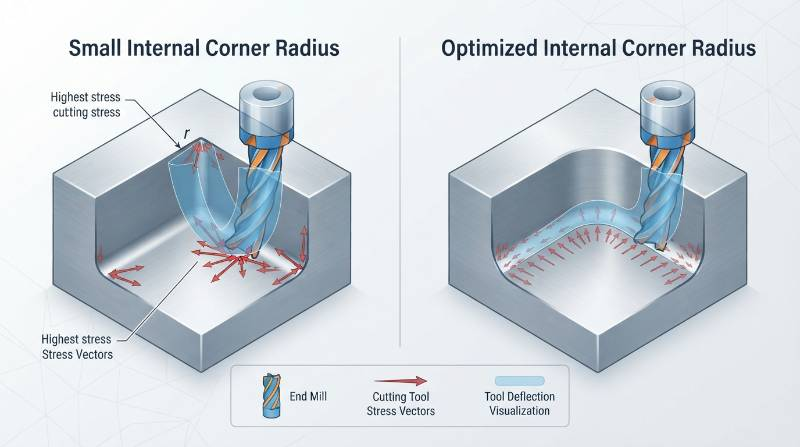
1. Geometric Feature Errors: Sharp Internal Corners and Unmachinable Radii
A frequent error in 3D CAD modeling is specifying perfectly sharp, 90° internal vertical corners in pockets or enclosed slots. Because rotating end mills cut with cylindrical geometry, milling an internal vertical right angle is physically impossible.
Attempting to produce sharp inside corners requires secondary Electrical Discharge Machining (EDM) or broaching operations. This adds extra fixturing setups, cycle time, and production overhead.
A related error is designing an internal corner radius that exactly matches the cutter radius (e.g., a 3.0 mm corner radius cut with a 6.0 mm diameter end mill). When a cutter enters a matching corner radius, the tool contact engagement angle jumps from 90° to 180° instantly.
This spike in radial tool engagement leads to severe tool chatter, surface gouging, and accelerated cutter wear. To maintain smooth continuous pathing and feed rates during precision CNC milling services, corner radii should be designed at least 15% to 30% larger than the tool radius.
Practical Geometry Corrections for Internal Corners
- R ≥ 1.15 × Cutter Radius: For an 8 mm cavity milled with a 6 mm end mill (3 mm radius), specify an internal corner radius of at least 3.5 mm to allow the tool to transition smoothly without stopping.
- Dog-Bone or T-Bone Reliefs: For interlocking rectangular parts or PCB mating enclosures requiring sharp male corners to seat flush, design dog-bone undercut reliefs.
- Floor Radii Balancing: Provide a bottom floor radius (e.g., 0.5 mm to 1.0 mm) matching common corner-radius bull-nose end mills to extend tool life.
2. Pocket Depth and Cavity Aspect Ratio Oversights
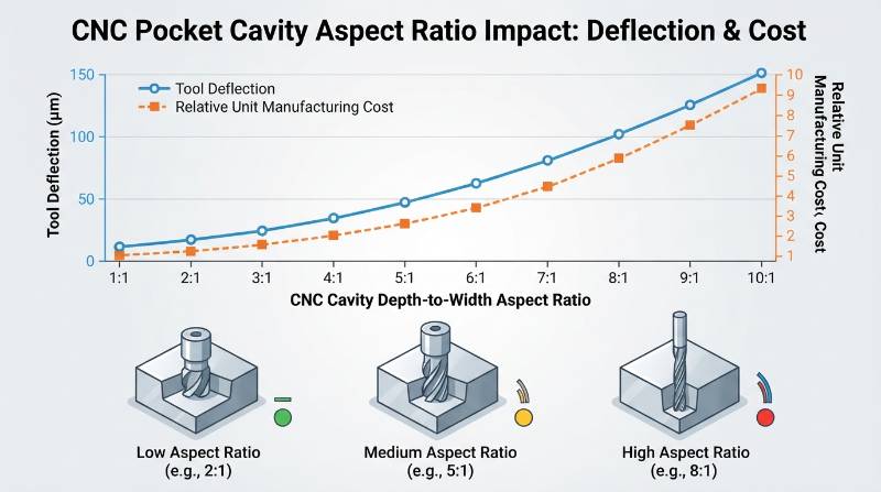
Designing deep, narrow pockets creates severe machining challenges. Standard milling tools operate reliably at pocket depth-to-width aspect ratios up to 3:1 or 4:1.
When pocket cavity depth exceeds 4× the cutter diameter, cutting tool reach must be extended. As demonstrated by the beam deflection equation, extended reach causes dimensional taper, harmonic resonance, and chip packing.
H: Pocket cavity depth (mm), W: Pocket minimum cavity width / cutter diameter (mm). Target: H/W ≤ 4:1 for standard milling; H/W > 6:1 requires specialized stepped-neck tooling.
Deep pocket milling also traps chips at the cutting zone. When chips are recut instead of evacuated by high-pressure through-spindle coolant, cutting edges chip and internal surface finishes degrade.
If deep cavities cannot be avoided, incorporate a 1° to 3° draft angle on the pocket sidewalls. Sidewall draft provides clearance for tapered high-rigidity tool shanks, minimizing vibration.
3. Thin Walls, Unsupported Ribs, and Clamping Distortion
Thin walls and tall, unsupported ribs are susceptible to deflection under cutting pressure, mechanical clamping, and internal residual stress release. As wall thickness decreases, the raw material loses structural stiffness, leading to chatter and dimensional variation.
In aerospace alloys like Al 7075-T651 or titanium Ti-6Al-4V, asymmetric material removal releases locked-in residual stresses, causing thin walls to bow after release from the machining fixture.
Review the baseline limits in our engineering CNC materials guide to balance component weight reduction with structural machining stiffness.
| Material Class | Alloy / Grade | Min Safe Wall (Standard) | Min Wall (Precision Setup) | Max Height-to-Thickness |
|---|---|---|---|---|
| Aluminum Alloy | Al 6061-T6 | 0.8 mm (0.031 in) | 0.5 mm (0.020 in) | 10:1 |
| Aerospace Alloy | Al 7075-T651 | 0.7 mm (0.027 in) | 0.4 mm (0.016 in) | 12:1 |
| Stainless Steel | AISI 304 / 316L | 1.0 mm (0.039 in) | 0.6 mm (0.024 in) | 8:1 |
| Titanium Alloy | Ti-6Al-4V (Grade 5) | 0.8 mm (0.031 in) | 0.5 mm (0.020 in) | 9:1 |
| Engineering Plastic | PEEK / POM-C | 1.5 mm (0.059 in) | 1.0 mm (0.039 in) | 6:1 |
4. Tolerancing and GD&T Specification Pitfalls
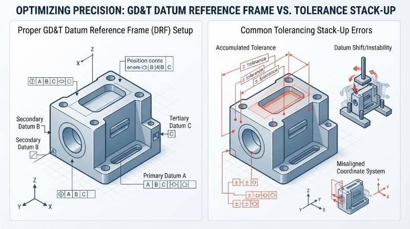
Applying uniform, tight tolerances across non-critical features is a common driver of unnecessary manufacturing costs. Specifying ±0.005 mm on non-critical clearance pockets forces slow cutting feeds, specialized tooling, and repeated CMM quality checks.
Relying on standard general tolerances like ISO 2768-m (e.g., ±0.1 mm to ±0.2 mm for mid-range lengths) for clearance features keeps machining costs practical. Reserve tight positional and dimensional controls for critical bearing bores, dowel locators, and sealing surfaces.
In Geometric Dimensioning and Tolerancing (GD&T) per ASME Y14.5M, improper Datum Reference Frame (DRF) alignment often causes inspection conflicts. Selecting small, non-machined, or non-parallel features as primary datums amplifies measurement variation.
Ensure your surface roughness specifications (Ra) align with dimensional tolerances. Demanding a tolerance of ±0.005 mm alongside a coarse surface roughness of Ra 3.2 μm is conflicting: peak-to-valley surface variations can exceed the allowed dimensional band.
5. Hole and Threading Design Deficiencies
Thread design errors frequently cause tap breakage during blind hole tapping. A common mistake is modeling threads that extend completely to the bottom of a blind drilled hole.
Standard cutting and forming taps have chamfer leads (1.5 to 3 thread pitches) that cannot cut full threads to the absolute bottom of a hole. Without sufficient depth clearance, chips compress at the hole bottom, breaking the tap.
L_drill: Total hole depth (mm), L_thread: Effective full thread depth (mm), P: Thread pitch (mm), D: Drill diameter (mm), with 0.3 × D accounting for standard 118°/140° drill point cone.
Specifying thread engagement depths greater than 2× to 2.5× the nominal fastener diameter offers minimal structural benefit. In steel and aluminum, over 80% of the mechanical fastener load is carried across the first 4 to 6 threads. Excess thread depth increases tool wear without adding holding strength.
6. Setup Inefficiencies: Multi-Sided Features vs 5-Axis Single-Setup Machining
Designing features on five or six faces of a prism without considering fixturing access forces multiple manual part flips. Every time an operator repositions a workpiece in a 3-axis vice, fixture positioning and datum pickup errors stack up (±0.015 mm to ±0.04 mm).
Accumulated setup drift can throw critical geometric relationships out of specification, including perpendicularity, true position, and concentricity across opposing faces.
Utilizing advanced 5-axis CNC machining centers solves this alignment issue. 5-axis single-setup machining allows full spindle access to 5 faces simultaneously, eliminating manual refixturing error and ensuring tight positional tolerances.
7. Post-Processing and Surface Coating Dimensional Neglect
Failing to account for coating thickness shifts is a frequent cause of assembly failure in precision components. Anodizing, electroplating, and chemical conversion coatings alter finished part dimensions.
Standard Type II sulfuric anodizing builds up roughly 10 μm to 25 μm total, with 50% penetration into the substrate and 50% outward surface growth (5 μm to 12.5 μm per surface). Type III Hard Anodizing adds 25 μm to 50 μm of outward surface growth per side.
This dimensional shift reduces internal bore diameters by double the coating growth and increases external pin diameters correspondingly. Close-tolerance bearing journals and high-class tapped threads (e.g., 6H) must be pre-machined undersized or masked before surface treatment.
Engineering drawings should explicitly state whether tolerance dimensions apply before coating (“Pre-Plate Dimensions”) or after coating (“Final Dimensions Apply After Plating”).
Comprehensive DFM Trade-Off Analysis: Feature Pitfalls, Cost Impacts, and Engineering Solutions
Balancing functional mechanical requirements with practical machining limits requires careful trade-offs. The following matrix outlines common geometry choices, their production impacts, and verified DFM solutions.
| Design Feature | Manufacturing Failure Mode | Relative Cost Multiplier | Recommended DFM Rule |
|---|---|---|---|
| Sharp Internal Vertical Corner | Requires Sinker EDM; high cycle time & electrode wear | 2.5× to 3.5× | Add radius R ≥ 1.15 × tool radius, or design dog-bone relief |
| Deep Narrow Pocket (> 6:1 Aspect) | Tool deflection, severe chatter, poor surface Ra & chip packing | 2.0× to 4.0× | Limit depth ≤ 4× width; add 1° to 3° sidewall draft |
| Ultra-Thin Unsupported Wall (< 0.5 mm) | Vibration deflection, part warping, and residual stress bending | 1.8× to 3.0× | Maintain ≥ 0.8 mm wall thickness; add cross-rib stiffeners |
| Over-Specified Blanket ±0.005 mm | Excessive CMM inspection time, high scrap rates, slow cutting feeds | 3.0× to 5.0× | Use ISO 2768-m for non-critical features; isolate tight limits to critical fits |
| Blind Hole Thread to Bottom | Tap bottoming impact, chip jamming, broken tap scrap | 1.5× to 2.5× | Add unthreaded drill relief of at least 2× to 3× pitch depth |
| Coating Thickness Ignored on Bores | Bores undersized post-anodize; fasteners bind in threads | Rework/Scrap | Pre-calculate layer build-up (+10 to +25 μm) on 2D drawings |
Extreme Niche Benchmark: Eliminating Chatter and Scrap in Al 7075-T651 Thin-Walled Optical Housings
High-precision optical and aerospace housings present demanding machining challenges. These components frequently combine thin structural walls (thickness < 0.8 mm), deep cavity aspect ratios (> 6:1), and tight bore tolerances (±0.005 mm) in stress-sensitive Al 7075-T651.
In a recent multi-axis aerospace manufacturing run, initial prototype attempts by a customer resulted in a 42% scrap rate due to thin-wall vibration, bore out-of-roundness, and post-machining stress distortion exceeding 0.035 mm.
Tyneen’s engineering team re-engineered the manufacturing process by implementing targeted DFM and machining optimizations:
- Optimized Dynamic Milling Toolpaths: Replaced conventional plunging with trochoidal high-speed milling paths that maintain a constant 15° tool engagement angle, reducing peak radial cutting forces by 65%.
- Equi-Spaced Anti-Vibration Tooling: Utilized variable-helix solid carbide end mills with tuned harmonic damping holders to suppress regenerative chatter along the thin cavity walls.
- Two-Stage Stress Relief Machining: Implemented a roughing cycle leaving 0.5 mm stock, followed by an intermediate stress-relief thermal cycle before taking fine finishing cuts at 18,000 RPM.
- Single-Setup 5-Axis Indexing: Machined all optical bores and mounting faces in a single clamping setup on a DMG MORI 5-axis machining center, preventing datum shift.
The revised process achieved a 0% scrap rate across 500 production units, held optical bore circularity within 0.003 mm, and reduced total machine cycle time by 34%.
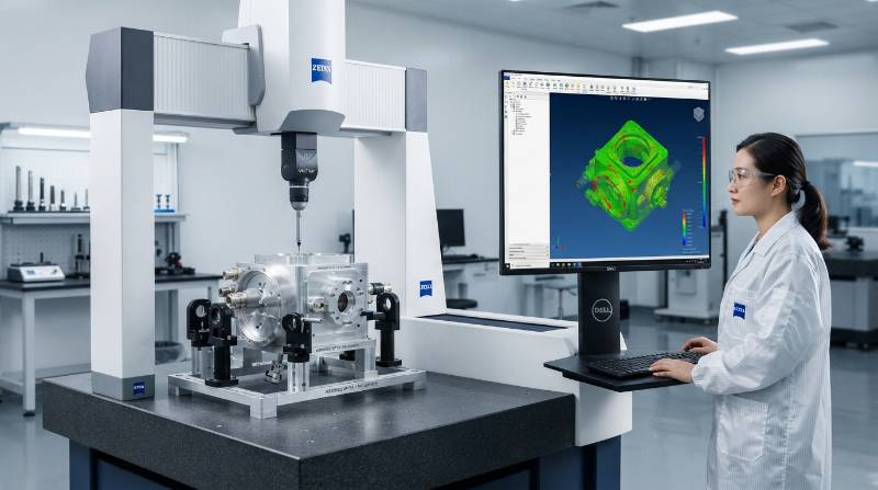
Tyneen Quality & Capability Verification: Certified Precision from DMG MORI Multi-Axis to Zeiss CMM
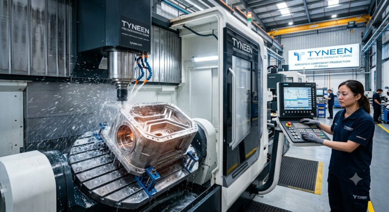
Preventing machining mistakes requires both DFM review and advanced production equipment. Tyneen operates a modern machining facility designed for high-precision components and complex geometric parts.
Our machine floor features DMG MORI and Mazak 3-axis, 4-axis, and 5-axis CNC machining centers, complemented by high-speed precision CNC turning capabilities with live tooling.
Our quality management system is certified to ISO 9001:2015, IATF 16949, and AS9100D standards. Every production run is verified using climate-controlled Zeiss 3D Coordinate Measuring Machines (CMM) achieving measurement accuracy down to ±0.001 mm.
Full dimensional inspection reports, material certifications, and First Article Inspection (FAI) reports per AS9102 are provided with production runs to confirm part compliance.
Actionable 3-Step Pathway: Eliminate CNC Machining Errors Before Cutting Metal
Engineering mistakes can be identified and resolved during early design stages. Tyneen provides a clear 3-step DFM engineering review process to validate your parts before cutting metal:
Precision DFM Verification & Production Workflow
- Step 1: Upload CAD Model & 2D Drawing
Submit your native 3D CAD files (.STEP, .IGES, or .SLDPRT) alongside 2D engineering drawings (.PDF) with critical GD&T specifications. - Step 2: Receive DFM Analysis & Instant Quotation in < 2 Hours
Our engineering team performs a thorough DFM review—evaluating corner radii, tool reach ratios, wall stability, and coating growth allowances. - Step 3: Precision Manufacturing & Zeiss CMM Verification
Parts are machined on multi-axis CNC equipment, verified with 100% CMM dimensional inspection, and dispatched worldwide.
To have our engineering team review your part geometry, check tolerances, and provide feedback, request a precision DFM quote today.
Frequently Asked Questions (FAQ)
What is the most common design mistake in precision CNC machining?
The most common design mistake is specifying sharp 90° internal vertical corners in pockets. Because CNC end mills are round, machining sharp internal corners is physically impossible without expensive secondary EDM processing. Always specify an internal radius at least 15% larger than the cutter radius.
What is the minimum recommended wall thickness for machined aluminum?
For standard CNC milling in aluminum (such as Al 6061-T6 or Al 7075-T6), the recommended minimum wall thickness is 0.8 mm (0.031 in). While specialized high-speed multi-axis setups can achieve walls as thin as 0.4 mm to 0.5 mm, wall heights should follow an aspect ratio of ≤ 10:1 to prevent vibration and deflection.
How deep should a blind tapped hole be drilled?
A blind hole should be drilled to a total depth equal to the effective thread depth plus 2 to 3 thread pitches of tapping clearance, plus an extra 0.3× drill diameter allowance for the conical 118° or 140° drill tip. Thread engagement depth should generally range from 1.5× to 2.0× the nominal bolt diameter.
How do surface finishes and coatings affect tight machining tolerances?
Surface treatments like Type II or Type III hard anodizing add measurable surface build-up (typically 5 μm to 25 μm per surface). This outward growth reduces internal bore diameters and increases external shaft dimensions. 2D production drawings must explicitly indicate whether specified tolerances apply before or after surface finishing.