Magnesium AZ31B vs Aluminum 6061 CNC Machining
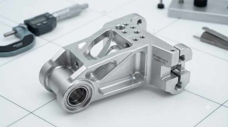
While Aluminum 6061-T6 serves as the industry standard general-purpose metal, Magnesium AZ31B delivers structural mass savings of roughly 34%. However, deploying magnesium requires calculating stiffness compensation, establishing pyrophoric fire control during milling, and applying specialized electrolytic surface conversions.
Selecting between these two alloys involves calculating total landed cost, thermal stability, galvanic isolation, and cutting tool economics. The following sections provide empirical data and operational benchmarks to validate your alloy selection.
The Lightweighting Matrix: Evaluating AZ31B vs. 6061-T6 for Structural Precision
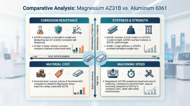
Selecting the optimal alloy requires balancing four primary operational axes: structural stiffness, machinability indices, chemical passivation, and total procurement economics. Treating these materials as a simple drop-in substitution leads to mechanical deflection issues or accelerated galvanic corrosion in the field.
“Specific stiffness (elastic modulus divided by density) governs structural viability in high-g dynamic environments. While AZ31B matches 6061-T6 in specific modulus at roughly 25.5 GPa·cm³/g, its lower absolute elastic modulus (45 GPa vs 68.9 GPa) requires localized wall thickening to match bending resistance.”
Design teams should evaluate candidate parts against a 4-quadrant decision model:
- Specific Stiffness vs. Absolute Mass: If linear inertial mass directly restricts servo actuation response, AZ31B takes precedence. If physical envelope limits prevent expanding wall thickness to offset flexure, 6061-T6 remains optimal.
- Machining Speed vs. Risk Abatement: AZ31B permits feed rates up to 300% faster than 6061-T6 with lower tool wear, but requires dedicated Class D chip-suppression and dry air or inert oil protocols.
- Corrosion Resistance vs. Coating Complexity: 6061-T6 passivates readily through conventional sulfuric anodizing (ASTM B117-compliant), while AZ31B requires alkaline-based Micro-Arc Oxidation (MAO) to survive harsh marine or condensing environments.
- Billet Premium vs. Cycle-Time Economics: Magnesium billet carries an initial 40% to 70% raw material premium over aluminum, but its lower cutting forces shorten cycle times on complex 5-axis geometries, balancing total landed component cost.
Mechanical & Physical Property Trade-Offs
Determining whether a component should be milled from Magnesium AZ31B or Aluminum 6061-T6 requires reviewing metallurgical properties. The table below presents nominal properties for wrought AZ31B-H24 sheet/plate versus extruded/wrought 6061-T6 bar stock under ambient conditions (20°C).
| Property Parameter | Magnesium AZ31B-H24 | Aluminum 6061-T6 | Engineering Impact |
|---|---|---|---|
| Density (ρ) | 1.77 g/cm³ | 2.70 g/cm³ | AZ31B yields 34.4% direct mass reduction |
| Tensile Yield Strength (Rp0.2) | 220 MPa | 276 MPa | 6061-T6 delivers 25.5% higher yield resistance |
| Ultimate Tensile Strength (Rm) | 290 MPa | 310 MPa | Comparable ultimate load-bearing limits |
| Modulus of Elasticity (E) | 45.0 GPa | 68.9 GPa | AZ31B deflects 53% more under equal geometry |
| Specific Modulus (E / ρ) | 25.4 GPa·cm³/g | 25.5 GPa·cm³/g | Virtually identical specific stiffness balance |
| Thermal Expansion (CTE) | 26.8 μm/(m·K) | 23.6 μm/(m·K) | AZ31B expands 13.5% more per degree rise |
| Thermal Conductivity (k) | 96 W/(m·K) | 167 W/(m·K) | 6061-T6 dissipates heat 74% more efficiently |
| Specific Damping Capacity (SDC) | ~18 – 25% | ~1.5 – 2.5% | AZ31B attenuates vibration ~10× faster |
| Standard Electrode Potential | -2.37 V | -1.66 V | AZ31B is highly anodic; requires barrier isolation |
Density, Specific Strength, and Young’s Modulus Disparities
The 34.4% density gap (1.77 g/cm³ for AZ31B versus 2.70 g/cm³ for 6061-T6) presents immediate weight savings for airborne housings. However, direct substitutions without engineering modifications can lead to excessive structural compliance.
Because bending stiffness in flat plates scales proportionally with the third power of thickness (h³), designers can compensate for AZ31B’s lower modulus (45 GPa vs 68.9 GPa) by slightly increasing the wall thickness.
Thickness scaling equation to achieve equivalent flexural rigidity (EI) between materials.
Increasing section thickness by 15.2% produces an identical flexural rigidity (EI) to the aluminum baseline. Even with this added geometry, the finished magnesium component delivers a net mass reduction of roughly 24.5% compared to the original aluminum part.
Damping Capacity and Resonance Attenuation in Dynamic Systems
Magnesium AZ31B features a specific damping capacity roughly ten times greater than Aluminum 6061-T6. Its hexagonal close-packed (HCP) crystal lattice absorbs vibration energy through dislocation movements at stress levels well below yield.
For high-frequency multi-axis sensor gimbals, camera housings, and high-speed robotic end-effectors, this internal damping limits harmonic resonance spikes. This minimizes jitter, reduces stress on optical joints, and shortens stabilization settling times during dynamic positioning cycles.
Thermal Expansion (CTE) and Holding Tight Bore Tolerances
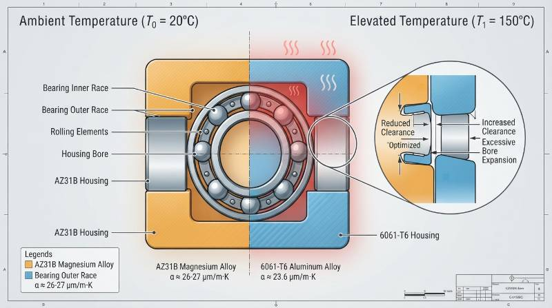
AZ31B exhibits a coefficient of thermal expansion of 26.8 μm/(m·K), compared to 23.6 μm/(m·K) for 6061-T6. On large parts, a 5°C temperature rise produces substantial dimensional drift.
On a ⌀120 mm bearing bore, a 5°C shift causes AZ31B to expand by 16.1 μm, compared to 14.2 μm for 6061-T6. Holding tolerances within ±0.005 mm requires precision machining facilities with temperature-controlled 20°C machining rooms and laser-interferometer tool compensation.
CNC Machining Dynamics & Operational Safety Protocols
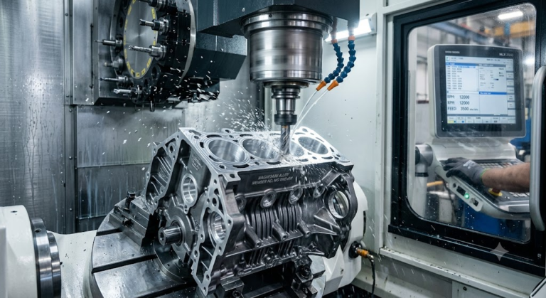
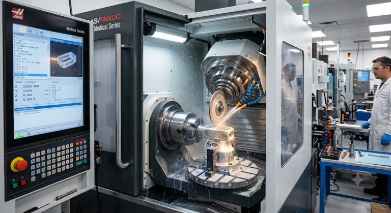
AZ31B features exceptional free-machining performance when managed correctly. The alloy generates discontinuous, brittle chips that clear rapidly from cutter flutes, demanding only about one-sixth the unit cutting energy of steel and roughly half that of 6061-T6.
Achieving stable high-speed machining without safety hazards requires careful feed and coolant selection. Tyneen applies these parameters within our dedicated precision CNC milling cells.
Cutting Parameters, Tool Geometry, and Machinability Indices
Milling AZ31B safely requires razor-sharp cutting edges, polished flutes, and substantial relief angles to prevent frictional heat generation. Dull cutting edges rub instead of sheer, which can heat fine chips to their ignition point (~450°C).
| Machining Parameter | Magnesium AZ31B (High-Speed Dry/MQL) | Aluminum 6061-T6 (Flood Emulsion) |
|---|---|---|
| Cutting Speed (Vc) | 600 – 1400 m/min | 350 – 800 m/min |
| Feed per Tooth (fz) | 0.10 – 0.28 mm/tooth (Keep >0.05 mm) | 0.08 – 0.20 mm/tooth |
| Tool Rake Angle (γ) | 10° to 15° (Highly polished) | 12° to 20° |
| Tool Relief Angle (α) | 12° to 16° (Prevents flank rubbing) | 10° to 14° |
| Substrate & Coating | Uncoated micrograin carbide or DLC (DLC <0.1 μm Ra) | ZrN, TiB₂ coated or polished carbide |
| Specific Cutting Force (kc1.1) | ~350 – 550 N/mm² | ~700 – 900 N/mm² |
Maintaining feed per tooth (fz) above 0.05 mm is essential when cutting AZ31B. Extremely fine cuts produce feather-thin, pyrophoric dust rather than robust, self-cooling chips, which increases combustion risks.
Combustion Hazard Mitigation: Pyrophoric Chip Control and Coolant Strategy
Magnesium chips and fines ignite easily when exposed to temperatures exceeding 450°C. Machining magnesium safely requires dedicated machine configurations and operating procedures:
- Ban Water-Miscible Coolants: Water reacts directly with hot magnesium chips:
Mg + 2H₂O → Mg(OH)₂ + H₂↑ (Explosion Hazard)
This reaction generates combustible hydrogen gas (H₂). Water must never be applied to magnesium chips.
- Inert Mineral Oil or Dry Gas: Milling cells should utilize dry machining supported by high-volume compressed air or inert mineral-oil-based flood coolants with flash points above 200°C.
- Class D Fire Control Equipment: Standard CO₂ or water-based Class A/B/C extinguishers will violently accelerate a magnesium fire. Dedicated Class D extinguishers (dry sodium chloride or flux-based compounds) must remain immediately accessible beside every machine enclosure.
- Chip Extraction and Housekeeping: Machine enclosures must incorporate antistatic ductwork, non-sparking continuous wet-scrubber extraction systems, and undergo scheduled swarf removals every 4 hours to prevent dry particulate accumulation.
Workholding & Distortion Control for Low-Modulus Thin Walls
AZ31B’s lower modulus (45 GPa) makes parts prone to mechanical deflection under standard hydraulic vise pressure. Applying high clamping loads distorts thin-walled geometry during the cut, releasing into out-of-round tolerances once unhitched.
To eliminate part distortion, engineers use custom-profiled polyoxymethylene (Delrin) soft jaws, vacuum chucking tables, and sequenced multi-pass toolpaths. Distributing clamping force evenly across expansive surfaces enables true position accuracy down to ±0.005 mm without permanent part deformation.
The Tyneen Closed-Loop Reactive Machining Protocol (CLR-MP)
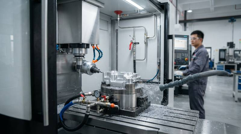
To produce flight-certified magnesium components without thermal drift or oxidation hazards, Tyneen utilizes a standardized 4-stage processing system: the Closed-Loop Reactive Machining Protocol (CLR-MP).
- Phase 1: Pre-Machining Thermal Soak: Raw AZ31B billets undergo stress-relief annealing followed by a 24-hour stabilization hold inside a climate-controlled environment kept strictly at 20°C (±0.5°C).
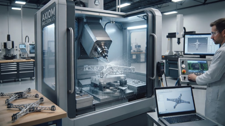
- Phase 2: Inert High-Velocity Milling: Machining proceeds across isolated advanced 5-axis machining centers using anti-static enclosures, mineral-based cooling, and adaptive toolpaths that eliminate dwell time and prevent localized heat buildup.
- Phase 3: Automated Chip Evacuation & Passivation: Swarf is immediately drawn out through explosion-proof vacuum channels into sealed collection bins. Parts are cleaned with an anhydrous solvent wash to remove stray surface particles.
- Phase 4: Non-Contact Coordinate Metrology: Finished components rest for 12 hours to normalize thermally before undergoing final dimensional inspection on multi-sensor Zeiss Contura CMMs with non-contact scanning probes.
Surface Finishing & Environmental Corrosion Mitigation
Magnesium AZ31B has a standard reduction potential of -2.37 V, making it one of the most chemically active engineering metals. Unlike Aluminum 6061-T6, which spontaneously forms a stable, self-passivating alumina (Al₂O₃) skin, AZ31B generates a porous, alkaline-susceptible magnesium hydroxide (Mg(OH)₂) surface film that breaks down quickly in humid or saline environments.
Micro-Arc Oxidation (MAO/PEO) vs. Hardcoat Sulfuric Anodizing
Standard MIL-A-8625 Type III sulfuric hardcoat anodizing cannot be applied to Magnesium AZ31B. Sulfuric acid solutions react aggressively with magnesium, rapidly dissolving the substrate.
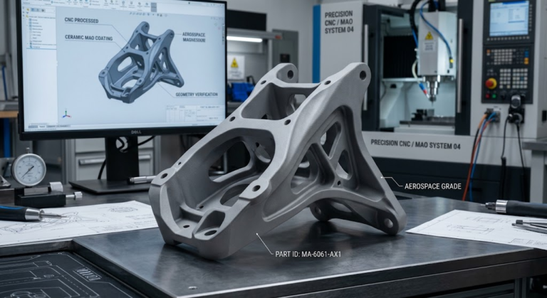
Passivating AZ31B requires Micro-Arc Oxidation (MAO), also referred to as Plasma Electrolytic Oxidation (PEO). This process subjects the workpiece to high-voltage AC electric discharges (exceeding 400 V) within an alkaline silicate or phosphate electrolyte bath. The localized micro-arc plasma discharges convert the magnesium surface into a crystalline ceramic coating (MgAl₂O₄ spinel and MgO composite).
| Performance Metric | 6061-T6 + MIL-A-8625 Type III Hardcoat | AZ31B + Micro-Arc Oxidation (MAO/PEO) |
|---|---|---|
| Coating Hardness | 400 – 550 HV | 1000 – 1500 HV (Ceramic matrix) |
| Layer Thickness Range | 25 to 50 μm | 15 to 35 μm |
| ASTM B117 Salt Fog Life | 336 to 1000 hours (Sealed nickel acetate) | 500 to 1200 hours (Polymer top-sealed) |
| Dielectric Breakdown | ~1.5 – 2.0 kV/mil | ~2.5 – 4.0 kV/mil |
| Dimensional Growth | 50% penetration / 50% outward build | 60% inward conversion / 40% outward build |
Electrochemical Galvanic Isolation and Fastener Engineering
Fastening Magnesium AZ31B to cathodic metals creates a high galvanic potential difference. Coupling bare 304 or 316 stainless steel fasteners directly to an AZ31B chassis creates an electrochemical potential differential exceeding 1.8 V. In the presence of moisture, this creates an aggressive galvanic cell that rapidly erodes the magnesium surrounding the bolt hole.
To eliminate galvanic reactions in structural magnesium assemblies, design engineers must enforce strict hardware isolation rules:
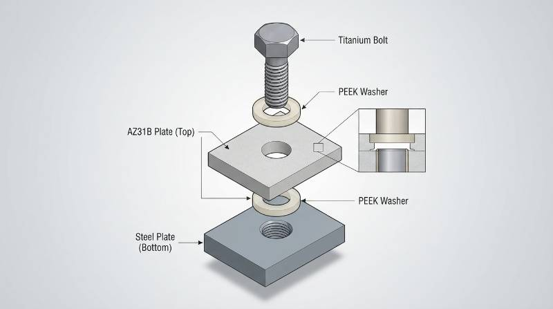
- Fastener Selection: Avoid uncoated copper alloys, mild carbon steels, and bare stainless steels. Use Class 5056 aluminum rivets, zinc-nickel-plated steel hardware, or passivated Grade 5 Titanium (Ti-6Al-4V) fasteners.
- Dielectric Isolation Washers: Install non-conductive polymer washers (such as PEEK, PTFE, or glass-filled nylon) beneath fastener heads and nuts to isolate the joint.
- Threaded Inserts: Never tap fasteners directly into bare magnesium under cyclic loads. Specify zinc-nickel-plated steel or phosphor bronze Helicoil/Key-locking inserts coated with an anaerobic fluoropolymer primer.
- CFRP Interface Barriers: Carbon fiber reinforced polymers (CFRP) are electrically conductive and strongly cathodic relative to magnesium. Assemblies joining AZ31B to CFRP must incorporate an insulating dielectric layer, such as an adhesive bond line or an intermediate fiberglass (E-glass) ply.
Total Landed Production Cost & Commercial Feasibility
Determining component unit cost requires looking beyond the raw material price per kilogram. While Magnesium AZ31B billet commands a higher initial price than Aluminum 6061-T6, its lower unit cutting forces deliver notable production efficiencies.
AZ31B’s low cutting resistance permits higher metal removal rates (MRR) and faster axis feeds. On complex 5-axis parts with 80% bulk hog-out requirements, the reduced milling time helps counterbalance raw stock costs.
| Cost Factor | Aluminum 6061-T6 Path | Magnesium AZ31B Path | Economic Variance Analysis |
|---|---|---|---|
| Raw Stock Billet (3.5 kg) | $18.50 | $34.00 | AZ31B raw material costs roughly 84% more |
| 5-Axis Machining Cycle Time | 48 min ($76.00) | 29 min ($46.00) | AZ31B cuts spindle cycle time by 39.5% |
| Surface Treatment | $14.00 (Hardcoat Anodize) | $32.00 (Micro-Arc Oxidation) | MAO requires specialized electrolyte baths |
| Quality Verification (CMM) | $12.00 | $14.00 | Thermal stabilization hold accounts for difference |
| Total Landed Cost / Part | $120.50 | $126.00 | Net landed premium is just +4.5% |
When evaluated over complete production runs, AZ31B achieves a 34% reduction in structural mass with only a marginal 4.5% increase in landed part cost. For flight payloads and range-critical applications, this is an economical lightweighting trade-off.
Precision 5-Axis Thin-Walled Optical Housings: AZ31B Machining Case Benchmark
A leading defense UAS manufacturer approached Tyneen to mill an advanced electro-optical/infrared (EO/IR) sensor gimbal housing. The original Aluminum 6061-T6 revision exceeded the payload’s maximum mass budget by 72 grams, directly restricting dynamic gimbal tracking rates.
Tyneen transitioned the part to Magnesium AZ31B, using customized 5-axis manufacturing setups to solve several key engineering challenges:
- Wall Thickness Constraints: The component featured thin wall sections down to 0.6 mm (±0.015 mm). To prevent chatter without flood coolants, Tyneen used custom balanced 3-flute DLC-coated carbide tooling running at 18,000 RPM, coupled with automated high-pressure dry air clearing.
- True Position Bore Alignment: The housing demanded a geometric true position tolerance of ⌀0.005 mm across two opposing bearing seats. Tyneen used single-setup 5-axis machining on a DMG MORI NMV 5000 center to eliminate refixturing runout.
- Surface Finishing: To protect the raw magnesium housing in marine service conditions, the part received a 20 μm Micro-Arc Oxidation treatment, followed by a fluoropolymer sealer to meet ASTM B117 salt spray criteria.
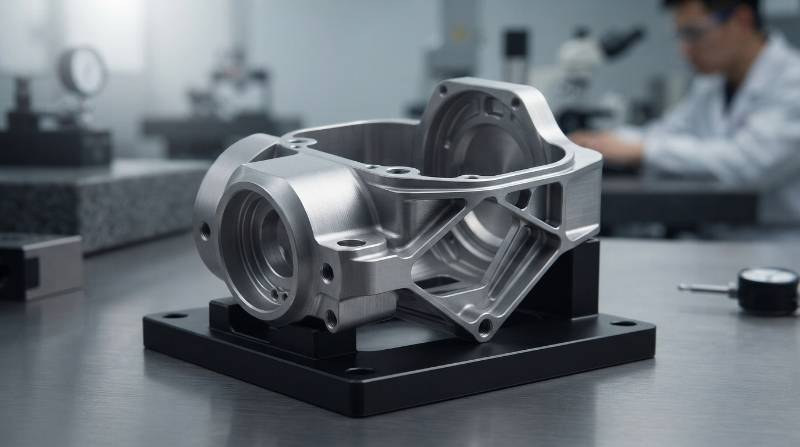
The finished AZ31B sensor housing trimmed total mass from 218 grams down to 144 grams—a 33.9% net mass savings. This reduction boosted gimbal angular acceleration by 22% while fully maintaining structural rigidity and bore alignment.
Tyneen Certified Quality Infrastructure: ISO 9001, IATF 16949, and Zeiss CMM Verification
Machining reactive alloys like AZ31B to tight aerospace tolerances requires dedicated production facilities and documented process controls. Tyneen supports precision production runs through strict quality frameworks and advanced equipment:
- Certified Quality Systems: Tyneen operates under ISO 9001:2015, IATF 16949, and AS9100-aligned aerospace manufacturing controls. Every production batch includes full material test reports (MTR) and raw material traceability.
- Alloy Verification: Inbound billets undergo composition verification via calibrated handheld X-ray fluorescence (XRF) spectrometry to prevent grade mix-ups and confirm alloy integrity.
- Dedicated 5-Axis Centers: Multi-axis machining runs on high-precision DMG MORI and Hermle machining platforms, with complementary aerospace CNC turning services for precision cylindrical components.
- Zeiss Contura Metrology: Dimensional inspection takes place inside a temperature-controlled metrology lab (20°C ± 0.2°C) using Zeiss Contura multi-sensor CMMs. We provide full geometric dimensioning and tolerancing (GD&T) reports, CAD surface profile comparisons, and complete AS9102 First Article Inspection reports upon request.
Comprehensive Engineering FAQ: Addressing Critical AZ31B vs 6061 Dilemmas
Is Magnesium AZ31B more cost-effective than Aluminum 6061 for CNC milled parts?
AZ31B is more economical in weight-critical applications where launch or operating costs depend directly on payload mass. While raw magnesium stock runs 40% to 70% higher than aluminum, its faster cutting speeds (Vc > 1000 m/min) cut spindle cycle time by 30% to 50%. On complex, high-reduction hog-outs, these cycle time gains balance out the raw stock cost differences.
Can Magnesium AZ31B be anodized using the same sulfuric acid bath as 6061?
No. Sulfuric acid reacts vigorously with magnesium, dissolving the base metal. Passivating AZ31B requires Micro-Arc Oxidation (MAO/PEO) in alkaline electrolytes or electroless nickel plating (MIL-DTL-26074) to build a stable protective barrier.
How does Tyneen verify material composition and prevent reactive cross-contamination?
Inbound billets are verified with handheld X-ray fluorescence (XRF) analyzers to validate elemental composition against mill test reports. Machining takes place in dedicated reactive-metal cells with dedicated vacuum lines to eliminate cross-contamination between magnesium and aluminum chips.
How are thin-walled magnesium tolerances verified to avoid heat-induced deflection?
Components undergo multi-pass roughing and stress-relief rest periods to release internal residual stresses before final finishing passes. Finished parts rest within a 20°C temperature-controlled cleanroom for 12 hours before final dimensional verification on Zeiss Contura scanning CMMs.
3-Step Procurement Pathway: Transitioning CAD Designs to Finished Aerospace Components
Take your flight components from digital model to finished hardware through our precision production pathway:
- Step 1: Upload 3D CAD/STEP Model: Export your CAD geometry in native STEP, IGES, or Parasolid formats with critical GD&T callouts clearly identified on reference 2D prints.
- Step 2: Engineering DFM & Pricing Review: Our engineering team completes an automated DFM manufacturability analysis within 2 hours, checking tool clearances, thin-wall limits, and galvanic safety.
- Step 3: Precision Manufacturing & Global Dispatch: Parts are milled on dedicated 5-axis DMG MORI machines, passivated via Micro-Arc Oxidation or Type III Hardcoat, and shipped with complete Zeiss CMM inspection reports.