Aerospace Magnesium Alloy CNC Machining Guide

Technical Evaluation Framework: Assessing Aerospace Magnesium Machinability
Aerospace magnesium CNC machining requires a multi-physics production strategy balancing an ignition threshold of 473°C (883°F), a low elastic modulus of 45 GPa (6.5 Msi), and an elevated coefficient of thermal expansion of 26 × 10⁻⁶/K. To deliver flight-qualified hardware, production facilities must shift from standard non-ferrous milling workflows to an enclosed Class D combustible material containment regime governed by NFPA 484 standards.
Water-miscible coolants are strictly prohibited during magnesium cutting operations because water dissociates on contact with finely divided hot magnesium, generating flammable hydrogen gas according to the reaction Mg + 2H₂O → Mg(OH)₂ + H₂↑. Instead, manufacturing flight hardware requires flood application of anhydrous synthetic mineral oils with flashpoints exceeding 160°C (320°F) or inert argon atmospheres. Evaluating production suitability requires analyzing our specialized aerospace material capabilities across structural stability, flammability barriers, and micro-machining parameters.
“Aerospace-grade magnesium machining efficiency depends directly on heat dissipation through continuous chip formation, maintaining cutting temperatures below 200°C (392°F) across spindle velocities above 1,200 m/min (3,937 SFM).”
Aerospace Metallurgy: Elektron 43 (WE43) vs Structural AZ31B
Elektron 43 (WE43B-T6 per AMS 4446 / ASTM B80) achieves a tensile yield strength of 220 MPa (31.9 ksi) and retains structural creep resistance up to 250°C (482°F), whereas standard AZ31B-H24 (AMS 4377 / ASTM B90) drops yield performance past 120°C (248°F). WE43 leverages a rare-earth alloy matrix—containing 3.7% to 4.3% Yttrium and approximately 3% Neodymium and Heavy Rare Earths (HRE)—to form thermally stable intermetallic precipitates at grain boundaries, which prevents dislocation slip under elevated flight loads.
This metallurgical distinction makes WE43 compliant with strict FAA FAR 25.853 flammability mandates for commercial aircraft cabin interiors and military rotorcraft gearboxes. While wrought AZ31B remains an economical selection for secondary brackets, unpressurized electronic enclosures, and low-temperature fairings, flight-critical power transmission housings rely exclusively on rare-earth WE43B-T6.
| Engineering Parameter | Elektron 43 (WE43B-T6) | Structural AZ31B-H24 | Aerospace 6061-T6 (Ref) |
|---|---|---|---|
| Governing Standards | AMS 4446 / ASTM B80 | AMS 4377 / ASTM B90 | AMS 4027 / ASTM B221 |
| Density | 1.84 g/cm³ (0.066 lb/in³) | 1.78 g/cm³ (0.064 lb/in³) | 2.70 g/cm³ (0.098 lb/in³) |
| Tensile Yield Strength | 220 MPa (31.9 ksi) | 150 MPa (21.8 ksi) | 276 MPa (40.0 ksi) |
| Modulus of Elasticity | 44.2 GPa (6.41 Msi) | 45.0 GPa (6.53 Msi) | 68.9 GPa (9.99 Msi) |
| Thermal Expansion (CTE) | 26.7 × 10⁻⁶/K | 26.0 × 10⁻⁶/K | 23.2 × 10⁻⁶/K |
| Max Operating Temp | 250°C (482°F) | 120°C (248°F) | 150°C (302°F) |
Pyrophoric Risk Mitigation & NFPA 484 Machining Physics
Class D fire prevention during high-velocity magnesium milling requires maintaining an undeformed chip thickness above 0.05 mm (0.0020″) and keeping linear cutting temperatures below the 473°C (883°F) ignition limit. Machining risks spike when rubbing occurs; dull cutting edges push tool friction past the ignition point, causing micro-fine powder to auto-ignite.
Production safety protocols deployed across our precision CNC milling platforms incorporate continuous vacuum swarf extraction paired with Class D dry powder suppression agents (Met-L-X sodium chloride flux). Water, carbon dioxide, and halogenated fire suppressants are completely barred from machining cells, as they accelerate burning metal reactions.
hm: Minimum Chip Thickness (mm, must remain ≥ 0.05 mm to prevent ignition), fz: Feed per Tooth (mm/tooth), kr: Major Cutting Edge Angle, ae: Radial Depth of Cut (mm), D: Cutter Diameter (mm)
Vc: Surface Cutting Velocity (m/min), D: Cutting Tool Diameter (mm), n: Spindle Speed (RPM)
Tooling Geometries and Feed Rate Calculations for Magnesium
End mill geometries for magnesium require high rake angles of 15° to 25° and primary relief angles between 10° and 15° to eliminate rubbing against freshly cut surfaces. Tool substrates must use uncoated sub-micron tungsten carbide or polycrystalline diamond (PCD) tipped tooling polished to an internal flute roughness below Ra 0.1 μm (4 μin) to prevent built-up edge (BUE).
Avoid titanium-based PVD coatings (such as TiN, TiAlN, or AlTiN) when milling magnesium, as chemical affinity between titanium and magnesium matrices accelerates coating delamination. Instead, diamond-like carbon (DLC) coatings or bare, mirror-polished carbide substrates are used to reduce cutting resistance and clear chips smoothly away from the tool body.
- Spindle Speed & Cutting Velocity: Vc = 800 to 1,500 m/min (2,625 to 4,920 SFM) roughing; up to 2,000 m/min (6,560 SFM) finishing.
- Feed per Tooth (Chip Load): fz = 0.10 to 0.25 mm/tooth (0.004″ to 0.010″/tooth) roughing; never allow fz to drop below 0.05 mm/tooth (0.002″/tooth).
- Radial Engagement (ae): Maintain radial step-over above 25% of cutter diameter to ensure uniform chip formation without dwell rubbing.
- Axial Depth of Cut (ap): Optimize ap up to 1.5× cutter diameter depending on part rigidity and machine tool vibration dampening.
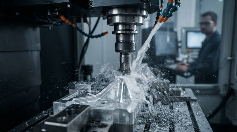
Precision GD&T Control: Overcoming Modulus Deflection and CTE Drift
Holding ±0.005 mm (±0.0002″) linear tolerances on thin-walled magnesium requires compensating for an elastic modulus of 45 GPa (6.5 Msi)—which deflects 36% more than standard 6061 aluminum under the same cutting forces—and an elevated CTE of 26 × 10⁻⁶/K. To prevent dimensional drift, all finishing operations are run inside a cleanroom envelope stabilized to 20°C ±0.5°C (68°F ±0.9°F).
Workholding systems rely on multi-point low-pressure hydraulic clamping (clamping force < 3.5 bar / 50 psi) combined with customized soft jaws and vacuum chucking to avoid residual clamping distortion. Thin webs down to 0.8 mm (0.031″) are cut using dynamic stepped down-milling toolpaths, alternating roughing cuts on opposing faces to relieve internal stock stresses without warping the workpiece.
Components also undergo roughing, semi-finishing, and final-pass cycles on our advanced machining services platforms. This isolates mechanical cutting pressures from critical datum features governed by ASME Y14.5M-2018 standards.
The Benchmark Aerospace Scenario: 5-Axis Precision Machining of WE43 Avionics & Gearbox Housings
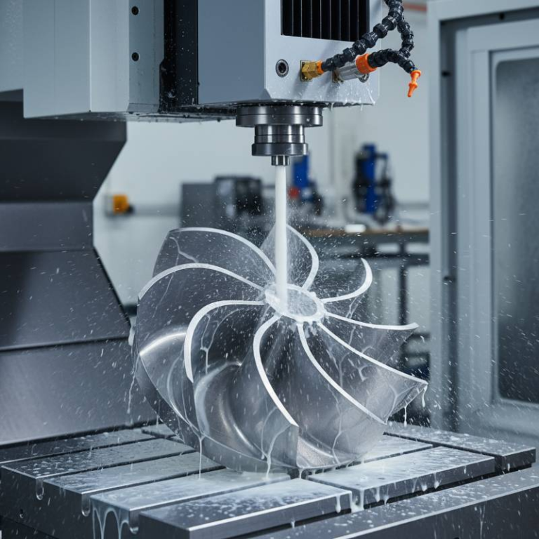
High-performance flight applications demand 5-axis simultaneous milling of weight-optimized Elektron 43 (WE43B-T6) helicopter auxiliary gearbox housings containing internal cross-drilled lubrication channels and thin perimeter walls. These components feature weight-saving pocket walls machined down to 0.8 mm (0.031″), deep intersecting internal oil galleries of ⌀3.2 mm (⌀0.125″), and tight bearing bore alignments requiring true position within ⌀0.012 mm (⌀0.0005″).
Machined on a DMG MORI monoBLOCK 5-axis platform, bearing journals are bored to circularity tolerances within 0.006 mm (0.00024″). Kinematic thermal error compensation pairs with in-spindle Renishaw RMP600 high-accuracy probing to update work coordinate offsets dynamically as ambient temperature shifts, ensuring the final part meets ASME Y14.5M requirements.
Tyneen’s 4-Phase Magnesium Precision Protocol (MPP)
Tyneen’s Magnesium Precision Protocol (MPP) eliminates unpredictable internal residual stress transformations and mitigates thermal expansion drift during tight-tolerance flight component manufacturing. This proprietary workflow includes four defined processing gates:
- Phase 1: High-Speed Roughing with NFPA Containment: Aggressive volumetric bulk stock removal leaves an offset envelope of 0.75 mm (0.030″) under flooded synthetic mineral oil cooling.
- Phase 2: Cryogenic Thermal Stress Stabilization: Parts undergo sub-zero thermal cycling from -80°C to +150°C (-112°F to +302°F) inside environmental chambers to relieve internal casting or extrusion stresses.
- Phase 3: High-Rake Finish Machining: Balanced high-speed finishing cuts with dynamic toolpath step-overs run at high spindle speeds, ensuring finished wall thicknesses down to 0.8 mm (0.031″).
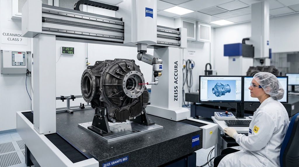
- Phase 4: In-Situ Probing & Zeiss Metrology: Part datums are checked with Renishaw RMP600 kinematic probes on the spindle before moving to a Zeiss PRISMO CMM inside a metrology lab held at 20°C ±0.5°C (68°F ±0.9°F).
Corrosion Mitigation & Post-Process Surface Passivation
Magnesium’s standard electrode potential of -2.37 V makes it naturally vulnerable to galvanic and pitting corrosion in salty or humid flight operating environments. Shielding structural airframe components requires multi-barrier chemical conversion and electrochemical surface passivation treatments.
Plasma Electrolytic Oxidation (PEO, such as Keronite) forms a dense, crystalline ceramic oxide layer (MgAl₂O₄ spinel) measuring 15 to 25 μm (0.0006″ to 0.0010″) thick, which provides dielectric protection and abrasion resistance. Alternatively, Tagnite anodizing or Dow 7/Dow 17 chemical conversion per AMS-M-3171, sealed with MIL-PRF-23377 high-solids epoxy primers, isolates components from oxidation.
| Passivation Treatment | Governing Specification | Layer Thickness Range | Salt Spray Resistance | Dielectric Breakdown |
|---|---|---|---|---|
| PEO / Keronite | Proprietary / ISO 14919 | 15 to 30 μm (0.0006″ to 0.0012″) | >1,000 Hours (ASTM B117) | >500 V/mil |
| Tagnite Anodize (Type II) | MIL-M-45202 / ASTM B893 | 10 to 20 μm (0.0004″ to 0.0008″) | >500 Hours (ASTM B117) | >300 V/mil |
| Chemical Conversion (Dow 7) | AMS-M-3171 Type III | 1 to 3 μm (0.00004″ to 0.00012″) | >96 Hours (ASTM B117) | Conductive / Non-dielectric |
| High-Solids Epoxy Primer | MIL-PRF-23377 Class C2 | 20 to 35 μm (0.0008″ to 0.0014″) | >2,000 Hours (System Matched) | Non-conductive barrier |
When bolting magnesium assemblies to carbon-fiber-reinforced polymer (CFRP) structural skins or titanium fasteners, direct contact will cause rapid galvanic degradation of the magnesium. Assembly protocols require non-conductive fiberglass (G10/FR4) insulating shims, cadmium-plated or passivated stainless fasteners coated with wet polysulfide sealant (AMS-S-8802), and strict isolation barriers to eliminate galvanic paths.
Aerospace Magnesium Engineering Trade-Offs: Elektron 43 vs AZ31B & Alternative Superalloys
Selecting Elektron 43 instead of Aluminum 6061-T6 cuts weight by 33% (1.84 g/cm³ versus 2.70 g/cm³), while offering higher specific yield strength for weight-critical spacecraft bus chassis and gimbal brackets. However, raw material billets for rare-earth WE43 cost roughly 4.5× more than 6061-T6 aluminum, and processing requires certified NFPA 484 combustible metal fire protocols.
Compared to laser powder bed fusion (LPBF) additive manufacturing using Scalmalloy or AlSi10Mg, 5-axis CNC machining from solid WE43 billets delivers fully dense, isotropic mechanical properties with zero internal gas porosity and eliminates hot-cracking vulnerabilities. This makes billet machining the superior choice for critical rotating components and pressurized hydraulic manifolds.
| Property / Metric | WE43B-T6 Magnesium | AZ31B-H24 Magnesium | Aluminum 6061-T6 | Titanium Ti-6Al-4V |
|---|---|---|---|---|
| Specific Yield Strength | 119.5 kN·m/kg | 84.3 kN·m/kg | 102.2 kN·m/kg | 188.7 kN·m/kg |
| Relative Raw Stock Cost | 4.5× (High) | 2.2× (Moderate) | 1.0× (Baseline) | 6.8× (Very High) |
| Relative CNC Machining Time | 0.75× (Fast) | 0.65× (Very Fast) | 1.0× (Baseline) | 3.8× (Slow) |
| Fire Safety Protocols | Strict (NFPA 484 Class D) | Strict (NFPA 484 Class D) | Standard Non-ferrous | Standard / Inert Gas |
| Surface Corrosion Barrier | PEO / Tagnite + Primer | Conversion + Primer | Sulfuric Anodize (Type II/III) | Passivated Native Oxide |
Tyneen AS9100D Quality Assurance, Class D Safety Architecture & Metrology Verification
Tyneen operates an AS9100D and ISO 9001:2015 certified production facility with verified ITAR compliance to support defense and flight hardware manufacturing. All production orders maintain comprehensive heat and melt-source traceability supported by chemical composition testing per ASTM E35 and mechanical certification reports matching AMS 4446 and AMS 4377 parameters.
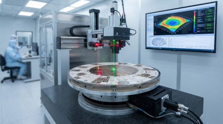
Final dimensional verification takes place inside a climate-controlled inspection lab (held at 20°C ±0.5°C / 68°F ±0.9°F) using high-precision coordinate measuring machines. Parts turned on our aerospace CNC turning centers or multi-axis machining centers are inspected on a Zeiss PRISMO Ultra 5-axis CMM with volumetric length measurement accuracy of MPEe = 0.9 + L/350 μm.
Every aerospace production shipment is accompanied by a full AS9102 First Article Inspection (FAI) report, complete raw material test certificates (MTR), and calibrated optical profilometer surface finish traces reaching Ra 0.4 μm (16 μin).
Frequently Asked Questions: Aerospace Magnesium CNC Machining
How do Tyneen machinists eliminate the risk of Class D magnesium chip fires?
Machining cells use anhydrous synthetic mineral oils with flashpoints exceeding 160°C (320°F) to prevent water-coolant hydrogen deflagration. We combine polished PCD tooling featuring positive rake angles (15° to 25°) with minimum chip thicknesses maintained above 0.05 mm (0.0020″) to prevent tool rubbing, supported by continuous swarf chip extractors and dedicated Class D dry-powder extinguishers at every machine enclosure.
What is the thinnest wall thickness attainable in CNC-machined Elektron 43?
Unsupported vertical walls can be reliably machined down to 0.8 mm (0.031″) over heights of up to 50 mm (1.97″), while reinforced pocket ribs can reach 0.5 mm (0.020″). Achieving these geometries without chatter requires balanced 5-axis toolpaths, dynamic step-down milling, and conformal vacuum clamping fixtures to compensate for magnesium’s lower 45 GPa (6.5 Msi) elastic modulus.
How does Tyneen prevent galvanic corrosion when magnesium connects to carbon composite or titanium?
Assembly interfaces receive a protective dielectric ceramic barrier using Plasma Electrolytic Oxidation (PEO) or hard Tagnite anodizing sealed with MIL-PRF-23377 epoxy primers. Physical assemblies are isolated using non-conductive G10 fiberglass shims and wet-installed with polysulfide sealant (AMS-S-8802) to block galvanic pathways against titanium or carbon composites.
Are Tyneen’s magnesium CNC operations compliant with ITAR and AS9100D aerospace standards?
Yes, Tyneen maintains active AS9100D, ISO 9001:2015, and IATF 16949 quality certifications alongside secure ITAR compliance protocols for handling defense data. We deliver full lot traceability, mill material test reports (MTR), and AS9102 First Article Inspection dossiers validated on our Zeiss PRISMO CMM platforms.
3-Step Procurement Action Pathway: Rapid Quoting to AS9102 Flight-Hardware Delivery
Aerospace procurement teams can initiate production orders through a streamlined risk-mitigation workflow that ensures intellectual property security and technical review before cutting begins. Uploading your 3D CAD models (STEP/IGES) provides direct access to our engineering team for actionable manufacturability analysis.
Every project follows our verified three-step production cycle:
- Step 1: Bilateral NDA Protection: Mutual non-disclosure agreements are processed within 1 business hour to safeguard proprietary defense and commercial CAD data.
- Step 2: 2-Hour DFM Engineering Review: Machining engineers evaluate part designs to identify thin-wall deflection risks, optimize cutter clearances, and identify cost-saving tolerance adjustments.
- Step 3: Multi-Axis Machining & Inspection: Parts are manufactured on 5-axis DMG MORI machines and verified on our Zeiss PRISMO CMM, shipping with a complete AS9102 First Article Inspection dossier.
Request an immediate engineering assessment by scheduling a DFM engineering consultation directly through our applications group.