Precision 5-Axis CNC Milling for Complex Aerospace Parts
High-Precision 5-Axis CNC Milling for Aerospace Components
Aerospace engineering demands components that defy the limits of traditional manufacturing. Our 5-axis CNC milling services specialize in the production of complex aerospace parts where failure is not an option. We deliver exceptional dimensional accuracy, consistently hitting tight tolerances of ±0.005mm (±0.0002 inches).
Surface integrity is paramount for aerodynamic efficiency and structural longevity. We achieve surface roughness finishes from Ra 0.8 μm down to Ra 0.4 μm, reducing the need for manual secondary finishing. This precision ensures that every component, from turbine blades to structural airframe brackets, meets the stringent requirements of modern flight.
By integrating high-speed spindles with advanced Aerospace CNC Machining Services, we eliminate the setup errors inherent in multi-op processes. Our facility is optimized for the subtractive manufacturing of geometries that were once considered unachievable.
AS9100D and ISO 9001:2015 Certified Manufacturing Excellence
Quality in aerospace is defined by rigorous documentation and repeatable processes. Tyneen operates under a strict Quality Management System (QMS) certified to AS9100D and ISO 9001:2015 standards. These certifications aren’t just badges; they govern every toolpath we generate and every material certification we verify.
“AS9100D is the international Quality Management System standard for the Aviation, Space, and Defense industry. It incorporates the entirety of ISO 9001 while adding specific requirements for safety, reliability, and technology.”
For our North American partners and global defense contractors, we maintain active ITAR (International Traffic in Arms Regulations) registration. This ensures that sensitive technical data and physical components are handled with the highest level of security and regulatory compliance. Every project undergoes a robust Quality & Compliance Standards review before the first chip is cut.
Kinematics of Precision: Simultaneous 5-Axis vs. 3+2 Positioning
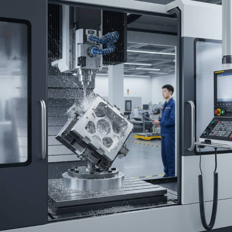
Understanding the kinematic difference between simultaneous movement and positional indexing is critical for aerospace part design. In simultaneous 5-axis machining, the X, Y, Z, A, and B axes all move concurrently. This allows the cutting tool to maintain a constant optimal angle of attack against complex curved surfaces.
In contrast, 3+2 axis positioning (or “indexed” machining) locks the two rotational axes in a specific orientation while the three linear axes perform the cut. While 3+2 is effective for reaching deep pockets, it often leaves “witness marks” at the transition points between different orientations.
| Feature | Simultaneous 5-Axis | 3+2 Positioning |
|---|---|---|
| Surface Finish | Superior (Continuous) | Good (Potential Transitions) |
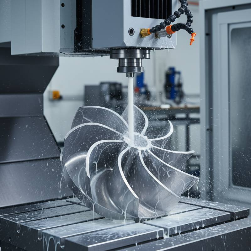
| Geometry Complexity | Impellers, Blisks, Porting | Prismatic parts with deep features |
| Toolpath Optimization | Complex Interference-Free | Standard CAD/CAM |
Our engineering team utilizes interference-free toolpath optimization to ensure that the tool holder never contacts the workpiece, even when navigating the tightest radii of an aero-engine blisk. This kinematics mastery directly translates to better surface integrity and longer tool life when working with hardened alloys.
The AeroPath-5 Precision Protocol: Our Proprietary Methodology
To meet the 2026 standards of aerospace manufacturing, we have developed the AeroPath-5 Precision Protocol. This methodology moves beyond standard CAD/CAM integration to address the physical realities of high-speed machining.
The protocol consists of three core pillars:
- AI-Driven Dynamic Simulation: We simulate the entire machining environment to predict and eliminate harmonic vibration in thin-walled aerospace parts.
- Real-Time Thermal Compensation: Our machines use sensors to adjust for micron-level thermal expansion in the spindle and ball screws during long-cycle production.
- Digital Twin Verification: Before the spindle turns, the toolpath is verified against a digital twin of the specific machine kinematic to ensure 100% collision avoidance.
Based on our internal data, the AeroPath-5 protocol has reduced scrap rates by 14% on complex titanium housings, ensuring that our customers receive their parts on time, every time.
Aerospace Material Expertise: Titanium, Inconel, and Superalloys
Machining aerospace-grade materials requires more than just a 5-axis machine; it requires deep metallurgical knowledge. We specialize in Advanced Material Capabilities, focusing on the “difficult-to-cut” alloys that define modern aviation.
Titanium Grade 5 (Ti-6Al-4V) is our specialty. Its high strength-to-weight ratio makes it ideal for structural components, but its low thermal conductivity requires precise coolant management and specialized carbide tooling. We also excel in milling Inconel 718 and other heat-resistant superalloys (HRSA) used in the hot sections of jet engines.
For airframe structures, we utilize Aluminum 7075-T6, employing high-speed machining (HSM) techniques to maintain part stability and prevent warping in large-scale components. Every material we use is accompanied by a full mill test report (MTR) for total traceability.
Secure Engineering Portal: NDA-Protected 3D Design Upload
Protecting your intellectual property is our primary concern. We offer a secure, encrypted engineering portal for the upload of sensitive 3D CAD files (STEP, IGES, Parasolid). Our standard workflow begins with a comprehensive Non-Disclosure Agreement (NDA) to protect your proprietary designs.

Our commitment to transparency continues through the inspection phase. We provide a downloadable AS9102 First Article Inspection (FAI) template and complete reports for all new parts. This ensures that the physical part matches the digital design in every dimension before full production commences.
Aerospace 5-Axis Milling FAQs
What are your typical lead times for aerospace 5-axis parts?
Lead times vary based on material availability and complexity, typically ranging from 2 to 6 weeks. We offer expedited services for AOG (Aircraft on Ground) situations where mission-critical parts are needed immediately.
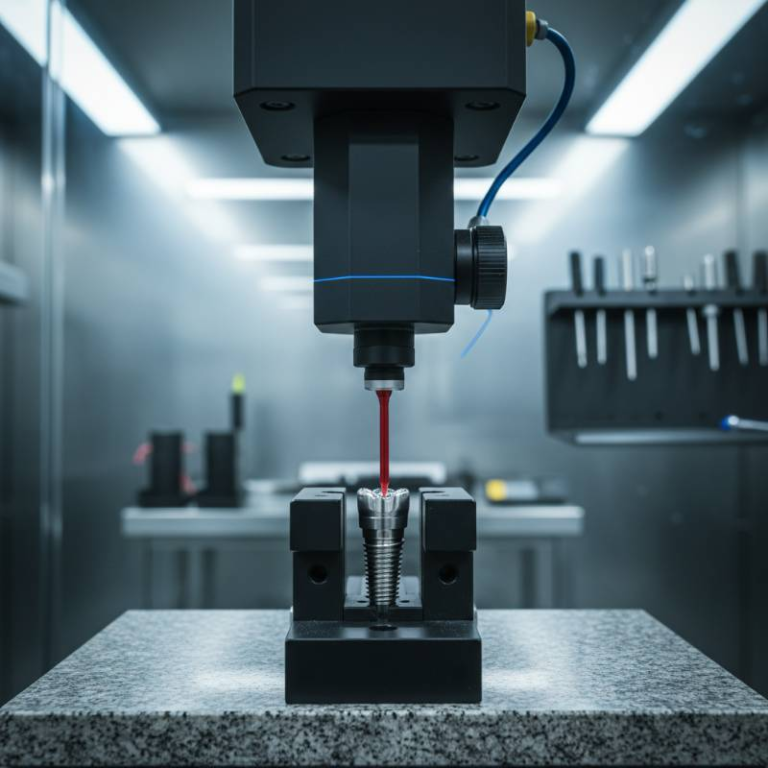
How do you verify the accuracy of complex geometries?
We use high-precision Coordinate Measuring Machines (CMM) with multi-sensor probes. This allows us to verify complex 3D contours against the original CAD model with micron-level accuracy.
Do you comply with SAE International standards?
Yes, our processes align with SAE International aerospace standards, ensuring that our manufacturing methods meet the global benchmark for safety and performance.
Can you provide carbon footprint reporting for parts?
As of 2026, we offer comprehensive environmental impact reports for each production run, helping our partners meet their sustainability and ESG goals within the aerospace supply chain.