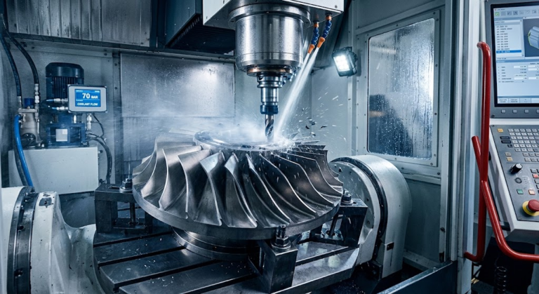
Wall Thickness Guide: Machined Plastics vs. Metals
The Structural Reality of CNC Thin-Wall Machining
CAD software permits engineers to model razor-thin partitions with absolute mathematical perfection. However, subtractive CNC machining transforms those models into physical parts via high-shear cutting forces, friction heating, and raw mechanical stress.
When an end mill engages raw stock, thin structural walls flex away from cutting edges, chatter uncontrollably, or warp permanently due to relieved internal stresses. Achieving feature success requires aligning geometric design directly with material physics.
Baseline machining thresholds differ fundamentally between material classes. Wrought aerospace alloys reliably support unsupported vertical walls down to 0.5 mm with aspect ratios reaching 10:1. Conversely, unreinforced engineering thermoplastics require a baseline minimum thickness of 1.0 mm to 1.5 mm, with height-to-thickness ratios rarely exceeding 3:1 without specialized tooling support.
The 5-Point Thin-Wall Machining Viability Framework
To avoid manufacturing failures on parts requiring aggressive weight reduction or compact internal packaging, production engineers evaluate thin-wall viability through a multi-physics framework rather than relying on static reference charts.
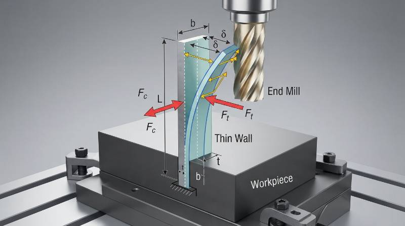
- Lateral Cutting Force Transfer: Quantifying radial cutting forces (Fr) that induce elastic bending moments on unsupported wall faces during end mill engagement.
- Geometry Aspect Ratio: Evaluating total unsupported height (H) against wall thickness (T). As H:T exceeds 4:1 in plastics or 8:1 in metals, harmonic chatter spikes exponentially.
- Thermal Accumulation and Dissipation: Balancing local friction heat at the tool-workpiece interface against the raw thermal conductivity (k) of the base stock to prevent plastic softening or thermal growth.
- Dynamic Fixturing Damping: Deploying custom soft jaws, conformal vacuum nests, or sacrificial low-melt support materials to back up flexible features throughout roughing and finishing.
- Metrology Verification Strategy: Selecting inspection methods that do not introduce mechanical contact errors, switching from standard tactile styli to non-contact optical scanning or ultra-low trigger force probes.
Fundamental Physics: Why Plastics and Metals Diverge Under the Spindle
The operational limits of metal and plastic parts diverge due to structural properties governing shear strain and thermal energy dissipation during chip formation.
Elastic Modulus Disparity and Mechanical Deflection Mechanics
Elastic modulus (Young’s Modulus, E) determines a material’s resistance to mechanical deflection under load. Aluminum 6061-T6 features an elastic modulus of ~68.9 GPa, whereas unfilled polyoxymethylene (POM-H Delrin) exhibits ~3.1 GPa, and virgin PEEK rates at ~4.0 GPa. Metals possess a 17- to 22-fold stiffness advantage over high-performance polymers, as outlined in our review of precision engineering materials.
When modeled as an idealized cantilever beam fixed at its base, wall deflection (δ) under concentrated lateral tool pressure follows classic structural beam theory:
δ: Deflection at top of wall (mm), Fc: Cutting force (N), H: Wall height (mm), E: Elastic Modulus (N/mm²), I: Second moment of area (b × T³ / 12)
Because thickness (T) is cubed in the moment of inertia calculation (I), halving wall thickness increases mechanical flexure by a factor of 8. When paired with a 20-fold drop in elastic modulus, a thin polymer wall deflects up to 160 times more than an identical aluminum wall under equal lateral cutting pressure.
Thermal Dynamics: CLTE, Dissipation, and Localized Plastic Memory
Metals conduct machining heat away from the cut zone rapidly. Aluminum 6061-T6 has a thermal conductivity of ~167 W/m·K, channeling heat into ejecting chips.
In contrast, unfilled polymers act as thermal insulators. Delrin exhibits a thermal conductivity of just 0.31 W/m·K, while virgin PEEK rates at 0.25 W/m·K. Machining heat remains concentrated at the cut point, triggering localized thermal expansion.
Compounding this behavior, the Coefficient of Linear Thermal Expansion (CLTE) of engineering polymers is vastly higher than that of metals. According to standard thermomechanical data from ASTM International, Aluminum 6061 expands at 23.1 × 10⁻⁶ /K, while Delrin expands at 110 × 10⁻⁶ /K and PTFE surges at 135 × 10⁻⁶ /K.
Unreinforced polymers expand up to 5 to 6 times more than aluminum per degree Celsius. As friction heats a flexible plastic wall, it expands outward directly into the rotating tool path, leading to over-cutting, wall gouging, and sub-surface thermal stress.
Residual Stress Profiles: Extruded Polymers vs. Stress-Relieved Wrought Alloys
Pre-machining stock preparation strongly dictates whether a thin wall will hold dimensional form post-cut. Wrought aluminum plate commonly ships in stress-relieved states, such as 6061-T651, which is mechanically stretched after heat treating per ISO 209 standards to neutralize inner tension.
Polymer stock, however, is manufactured via high-pressure extrusion or heavy-section casting. These processes cool unevenly from the outside inward, locking intense tensile forces into outer skin layers and compressive forces within the core.
Excavating material to form deep pockets relieves this internal balance. The remaining thin polymer wall bows, twists, or cups immediately upon release from the fixture unless the stock has undergone calibrated, multi-stage pre-machining annealing cycles.

Definitive Material Comparison: Minimum Wall Thresholds and Mechanical Properties
Selecting reliable wall geometry requires comparing structural limits and achievable tolerances across common alloy and polymer types.
| Material Class & Grade | Elastic Modulus (GPa) | Min Unsupported Wall (mm) | Min Supported Rib (mm) | Max Safe Aspect Ratio (H:T) | Standard Tolerance (mm) |
|---|---|---|---|---|---|
| Al 6061-T6 / 7075-T6 | 68.9 – 71.7 | 0.50 | 0.30 | 10:1 | ±0.010 |
| Stainless Steel 304 / 316 | 193.0 – 200.0 | 0.65 | 0.40 | 8:1 | ±0.015 |
| Titanium Ti-6Al-4V (Gr 5) | 113.8 | 0.60 | 0.35 | 7:1 | ±0.015 |
| PEEK (Unfilled 450G) | 3.8 – 4.2 | 1.00 | 0.80 | 4:1 | ±0.025 |
| PEEK-GF30 (30% Glass) | 9.5 – 10.5 | 0.75 | 0.50 | 6:1 | ±0.015 |
| Acetal / Delrin (POM-H/C) | 2.8 – 3.2 | 1.20 | 0.80 | 3.5:1 | ±0.030 |
| Nylon (PA66 Extruded) | 2.7 – 3.0 | 1.50 | 1.00 | 3:1 | ±0.050 |
| PTFE (Teflon) / UHMW-PE | 0.4 – 0.7 | 2.00 | 1.50 | 2:1 | ±0.080 |
Metal Thin-Wall Baselines: Aluminum, Stainless Steel, and Titanium
Lightweight aluminum structural alloys (such as 6061-T6 and 7075-T6) handle thin-wall operations exceptionally well when paired with high-speed spindles and optimized step-down passes. High-performance machine shops rely on advanced machining capabilities to mill freestanding walls down to 0.50 mm, and cross-ribbed pockets down to 0.30 mm.
Stainless steels (304 and 316) yield higher modulus figures (~193 GPa), but intense strain-hardening limits safe unsupported wall thickness to 0.65 mm. Heavy radial cutting pressure will deflect thinner features, generating high-frequency chatter that dulls carbide flutes rapidly.
Titanium Ti-6Al-4V provides exceptional strength-to-weight performance, but its lower elastic modulus (~114 GPa relative to steel) and poor thermal dissipation mean walls thinner than 0.60 mm are prone to dimensional tapering from tool push-off.
Engineering Polymer Baselines: PEEK, Delrin, Nylon, and Fluoropolymers
Plastics present unique machining limitations due to their viscoelastic behavior. When an end mill contacts unfilled Delrin or Nylon 6/6, the material deflects elastically before shearing into chips. Consequently, unsupported walls below 1.20 mm are difficult to machine reliably without tapered profiles or surface chatter.
Virgin PEEK offers superior structural stability among unfilled polymers, allowing unsupported features down to 1.00 mm. When reinforced with short glass fibers (PEEK-GF30), the modulus triples to ~10 GPa. This structural boost allows walls to reach 0.75 mm while maintaining aspect ratios up to 6:1.
Soft fluoropolymers like PTFE and semi-crystalline UHMW-PE represent the most challenging machining category. Lacking structural rigidity, they distort under light tool pressure. A reliable minimum wall baseline of 2.00 mm is mandatory to prevent torn edges or permanent deformation.
Toolpath Strategies and Workholding to Mitigate Chatter and Deflection
Cutting extreme thin-wall geometries requires dedicated CAM toolpaths and specialized part workholding. Traditional pocket roughing routines will quickly destroy delicate vertical features.
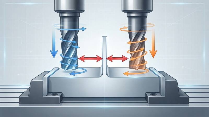
Dynamic Toolpath Kinematics: Step-Down Passes, High-Helix End Mills, and Climb Milling
Traditional milling workflows—such as clearing an entire cavity before addressing the adjacent pocket—leave thin divider ribs unsupported against full radial cut forces. This practice leads directly to chatter and wall failure.
Industrial setups deploy synchronized step-down levels across our precision CNC milling services. The cutter drops by axial increments (ap = 0.5 mm to 1.5 mm), clearing both sides of the rib in alternating sequences. The lower, unmachined core of the stock provides mechanical support for the upper rib throughout the cycle.
Tooling configurations require specific adjustments based on workpiece material:
- End Mill Geometry for Plastics: Polished, uncoated single- or double-flute carbide end mills with high rake angles (up to 18°) and razor-honed cutting edges ensure clean polymer slicing without plowing. Diamond-Like Carbon (DLC) coatings prevent melted chip adhesion.
- End Mill Geometry for Metals: High-helix tooling (45° to 50°) converts radial force components into axial forces directed into the machine spindle, protecting thin walls from lateral push-out.
- Milling Vector Control: Strict climb milling maintains uniform chip formation, directing cut vectors toward the supported base rather than flexing the unsupported top edge.
Advanced Workholding: Vacuum Chucks, Sacrificial Wax, and Cryogenic Cooling
Standard mechanical vise clamping introduces compressive stresses that buckle thin wall structures. Thin base plates and fragile ribs require uniform, non-deforming fixturing methods.
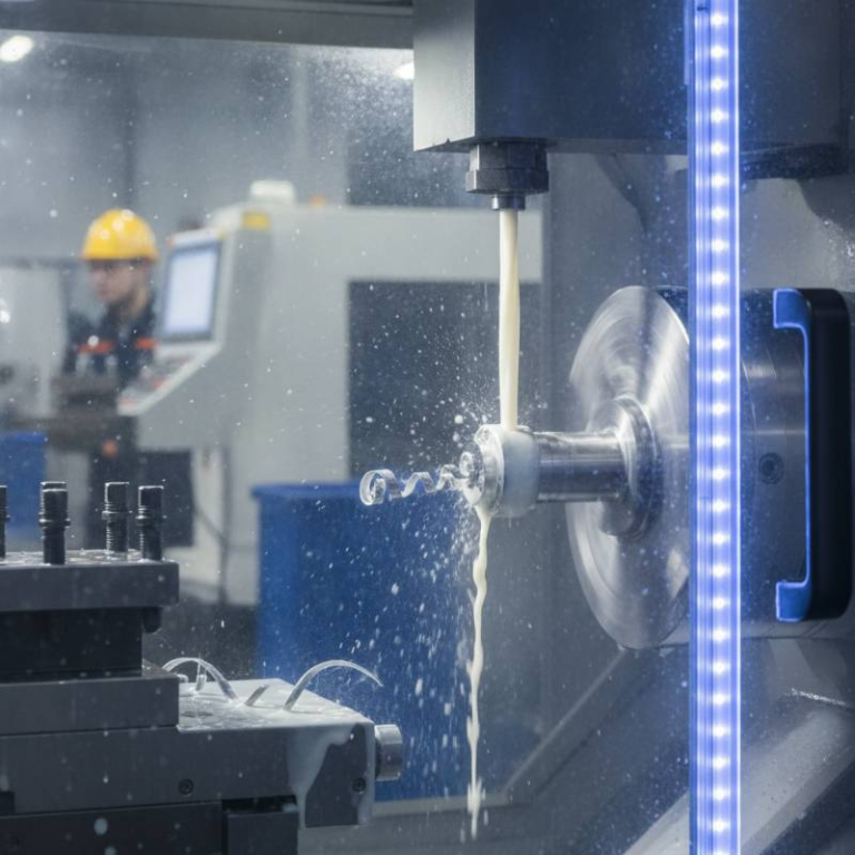
Precision porous ceramic vacuum chucks distribute holding force evenly across thin stock, eliminating distortion. In high-aspect deep pocket operations, machine setups use water-soluble fixturing waxes (such as Rigidax) or low-melting bismuth-tin alloys. These materials support machined cavities during secondary operations and melt cleanly away at 70°C without leaving residues.
Vortex tube cold-air guns or cryogenic CO₂ blasts provide localized chilling at -40°C. This counteracts the low thermal conductivity of polymers, freezing plastic chips crisp to prevent burr formation while maintaining wall rigidity during finish passes.
Quality Metrology and Post-Processing: Verifying Thin Walls Without Distortion
Measuring compliant walls requires specialized metrology techniques. Standard coordinate measuring machine (CMM) touch probes exert trigger forces between 0.075 N and 0.15 N. On a 1.0 mm plastic wall with a 5:1 aspect ratio, that contact force induces 0.015 mm to 0.030 mm of elastic flex, generating false non-conformance readings.
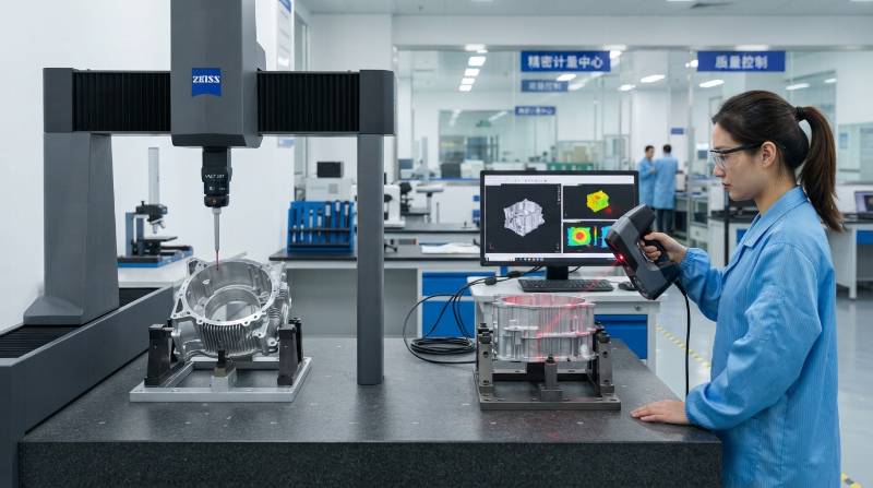
Tyneen verifies high-precision thin features using dedicated measurement protocols:
- Non-Contact Structured Light Metrology: Blue light 3D scanners capture surface point clouds without physical contact, verifying wall thickness profiles and GD&T true position across entire components.
- Low-Force Micro-Stylus CMM: Zeiss PRISMO setups with VAST active scanning heads operate at contact forces below 0.02 N, ensuring accurate tactile checks on flexible plastic ribs.
- Intermediate Thermal Stabilization Cycles: Semi-crystalline polymers undergo post-roughing annealing (e.g., PEEK at 200°C, Delrin at 160°C) with slow furnace ramps to eliminate residual stresses before final skim cuts.
High-Aspect-Ratio Thin Walls: 0.8 mm PEEK vs. 0.5 mm Aluminum in Deep Enclosures
A global aerospace client required an RF-isolated flight sensor chassis: a 45 mm deep enclosure featuring 0.8 mm unsupported PEEK dielectric barriers alongside 0.5 mm Aluminum 6061-T6 EMI shield partitions. The drawing called for true position tolerances of ⌀0.03 mm relative to datum surfaces, with surface finishes held to Ra 0.8 μm.
Conventional machining produced failed parts during initial tests: aluminum walls developed chatter at pocket depths past 25 mm, while PEEK barriers suffered heat-induced deflection and warped 0.12 mm out of position.
Tyneen’s engineering team redesigned the manufacturing approach:
- Toolpath Optimization: Replaced conventional pocketing with synchronized, alternating step-down passes using 3-flute 50° high-helix DLC end mills, maintaining structural stock support behind the walls throughout roughing.
- Thermal Management: Implemented cryogenic cold-air blasts across the PEEK features, preventing localized softening and maintaining material stiffness during cuts.
- Stabilization Routine: Introduced an intermediate stress-relief annealing cycle for the PEEK blanks prior to final finishing passes.
The revised process achieved 100% compliance across production batches, holding PEEK walls at 0.80 ±0.012 mm and aluminum partitions at 0.50 ±0.006 mm, validated via Zeiss optical non-contact scanning.
Certified Precision Infrastructure: Tyneen’s Multi-Axis Equipment
Reliable thin-wall machining requires rigid machine tools and precision spindle control. Tyneen operates certified production facilities meeting ISO 9001:2015, IATF 16949, and AS9100D aerospace standards.
Our machining floor features 3-axis, 4-axis, and simultaneous 5-axis DMG MORI machining centers alongside multi-tasking turning equipment. Spindle speeds reaching 24,000 RPM, paired with thermal compensation software, provide the toolpath dynamics and vibration control needed for thin-wall operations in challenging polymers and alloys. Explore our CNC turning and multi-tasking capabilities to see our full range of machine assets.
3-Step Production Pathway: Fast-Track Thin-Wall DFM to Scaled Manufacturing
Transitioning thin-walled parts from CAD models to finished production components requires upfront design validation and disciplined manufacturing control.
Launch Your Thin-Wall Production with Tyneen
- Upload 3D CAD & Technical Prints: Submit your STEP, IGES, or native CAD models alongside 2D PDF drawings detailing critical GD&T datums and thin-wall callouts.
- Comprehensive DFM Analysis & Rapid Quotation: Receive an automated DFM assessment covering wall thickness risks, aspect ratios, and material deflection profiles, alongside a guaranteed engineering quote in under 2 hours.
- Certified Multi-Axis Execution: Move from rapid-turn prototype sampling to scaled production, backed by full First Article Inspection (FAI), material test reports, and non-contact CMM verification.
Frequently Asked Questions About Thin-Wall Machining
Can plastic parts achieve the same thin wall thickness as aluminum in CNC machining?
In general production, no. Unreinforced engineering plastics like Delrin and Nylon require baseline unsupported walls of 1.0 mm to 1.5 mm, whereas Aluminum 6061-T6 routinely supports walls down to 0.5 mm. Plastics exhibit a much lower elastic modulus and poor thermal dissipation, causing thin ribs to flex away from cutting tools or deform under localized friction heat.
Is CNC machining thin-walled plastic parts more expensive than 3D printing or injection molding?
For production volumes below 250 units, CNC machining is generally more cost-effective than injection molding because it eliminates expensive tooling costs. Compared to industrial 3D printing, machining delivers superior isotropic strength and surface finishes (Ra 0.8 μm). However, thin polymer walls demand shallower step-downs, custom workholding, and lower feed rates, which increase machine cycle times relative to standard parts.
How do you verify wall thickness tolerances on flexible plastics without probe deflection errors?
Quality teams avoid standard high-force mechanical touch styli, which exert enough contact force (0.075 N to 0.15 N) to flex thin polymer walls and yield inaccurate measurements. We utilize structured-light non-contact optical scanning, high-resolution optical comparators, or active CMM styli calibrated to trigger forces below 0.02 N.
How does Tyneen control internal residual stress during thin wall machining?
Our process uses multi-stage stress management: stock pre-selection, intermediate stress-relief annealing between roughing and finish cuts, and balanced, symmetric material removal. This approach neutralizes skin-to-core stress differentials, ensuring finished parts maintain dimensional stability over time. For project evaluations, connect directly with the Tyneen DFM engineering team.