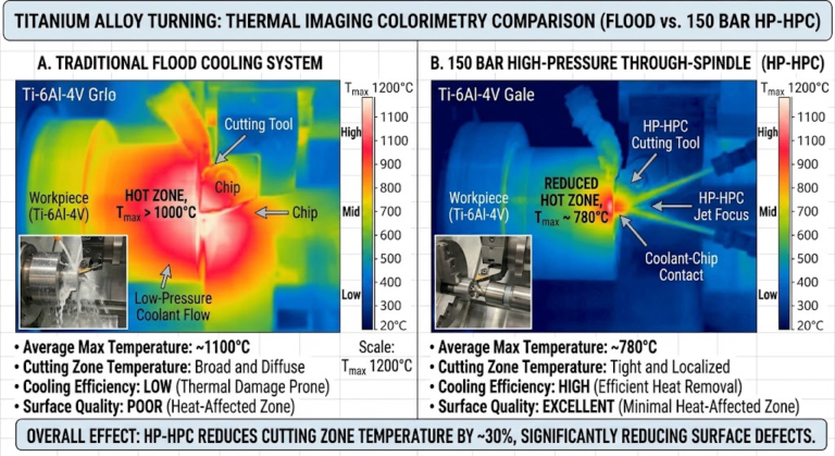
Carbon Fiber Machining for Racing Automotive Parts
High-Precision Carbon Fiber Machining for Racing Automotive Components
Precision carbon fiber machining for racing automotive parts utilizes high-speed 5-axis CNC routing with polycrystalline diamond (PCD) tooling to trim, drill, and pocket cured composite laminates without interlaminar shear failure. Operating at cutting speeds between 300 and 600 m/min under dry vacuum conditions, this specialized process achieves sub-0.02 mm tolerances while preserving the structural integrity of thin-walled aerodynamic panels and load-bearing chassis components.
In modern motorsport engineering—spanning Formula 1, WEC Hypercar, and GT3 platforms—weight reduction and aerodynamic stiffness dictate track dominance. Carbon-Fiber-Reinforced Polymers (CFRP) provide unmatched strength-to-weight ratios, but secondary machining operations present severe manufacturing risks.
Unlike homogeneous metals that yield predictably during chip formation, cured carbon laminates are inhomogeneous and abrasive. Substandard machining induces hidden micro-cracks, fiber breakout, and thermal damage to the polymer matrix, which compromises structural performance under race loads.
CFRP Machining Physics: Overcoming Anisotropy, Micro-Cracking, and Thermal Degradation
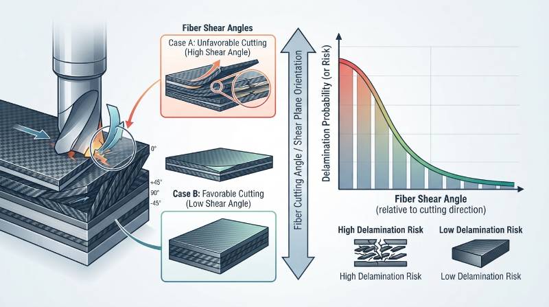
Machining CFRP is an abrasive fracture process rather than plastic shear deformation. As the cutting edge strikes high-modulus carbon fibers, it exerts alternating compressive, bending, and shear forces depending on fiber orientation relative to tool feed vectors.
Interlaminar Shear Stress: The localized force exerted perpendicular to stacked composite plies during tool entry or exit. Exceeding the matrix critical shear strength (typically 60–90 MPa in standard epoxy systems) triggers immediate delamination.
Thermal accumulation is a primary failure mode during dry composite routing. Carbon fiber laminates exhibit low transverse thermal conductivity (often below 1.0 W/m·K through-thickness), trapping friction-generated heat at the cutting interface.
If cutting interface temperatures surpass the matrix glass transition temperature (Tg)—which typically ranges from 120°C to 220°C depending on the resin system—the thermoset matrix softens. This softening leads to fiber pullout, structural degradation, and dimensional drift under race conditions.
Selecting optimized engineering materials and controlling cutting parameters ensures the laminate stays well below its thermal degradation threshold throughout the milling cycle.
Cutting Tool Selection: PCD vs. CVD Diamond vs. Coated Carbide
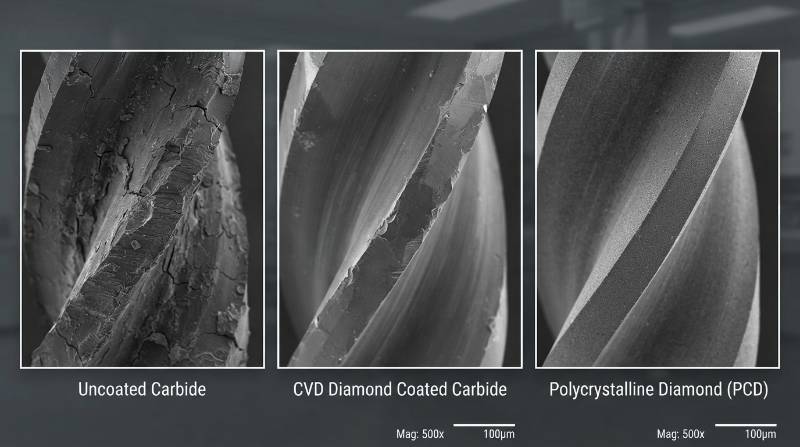
Uncoated tungsten carbide tools fail rapidly when machining carbon fiber. The high hardness of carbon filaments (approx. 3,000–5,000 HV) causes extreme abrasive flank wear on carbide edges within minutes, blunting the edge radius beyond the critical 10 µm threshold required to shear fibers cleanly.
| Tool Material / Geometry | Hardness (HV) | Tool Life Index | Edge Honing Limit | Delamination Risk |
|---|---|---|---|---|
| Uncoated Solid Carbide | 1,600 – 1,800 | 1.0x (Baseline: ~5m linear) | 2 – 4 µm | High (post 10 min run) |
| CVD Diamond Coated Burr | 8,000 – 10,000 | 8.0x – 12.0x | 6 – 10 µm | Low to Moderate |
| PCD Compression End Mill | 6,000 – 8,000 | 20.0x – 30.0x | 1 – 3 µm | Extremely Low (<0.5%) |
Compression Router Geometries
Compression end mills feature opposing helix angles—up-cut geometry at the bottom and down-cut geometry at the top. This geometry directs cutting forces inward toward the center of the composite stack.
By forcing the top and bottom plies into the core laminate rather than pulling them outward, compression cutters neutralize peel-up and push-out delamination during continuous profile edge trimming.
The Tyneen Zero-Delamination Composite Machining Protocol (ZD-CMP)™
To eliminate machining-induced composite scrap, Tyneen engineers developed the Zero-Delamination Composite Machining Protocol (ZD-CMP)™. This systematic, 4-stage manufacturing framework governs high-precision motorsport components:
- Adaptive Vacuum-Dynamic Fixturing: Thin, multi-curved aerodynamic shells flex under cutting pressure. We deploy custom CNC-machined polyurethane tooling board nests equipped with closed-cell micro-porous vacuum channels, delivering 95 kPa clamping forces directly below cut lines.
- Bi-Directional Climb-Cut Vectoring: Toolpaths are programmatically aligned with the surface prepreg weave angle. Climb milling ensures the tool enters the fiber bundle in compression, preventing ragged fiber fringe along aerodynamic splitters.
- Dual-Stage High-Velocity Particulate Evacuation: High-vacuum nozzles follow the toolhead within 5 mm of the cut point, extracting abrasive carbon dust before it can pack into cut kerfs and cause secondary thermal buildup.
- In-Line Non-Contact Laser Metrology: Finished profiles, mounting pockets, and countersinks are scanned directly on the machine bed using blue-light laser probes to verify edge integrity and ±0.01 mm dimensional compliance before un-clamping.
Explore our full scope of advanced machining services to see how we apply this methodology across complex multi-axis component production.
Motorsport Subsystems: Applications from Aero Splitters to Chassis Monocoques
Carbon fiber machining is essential across mission-critical racing subsystems where structural predictability directly impacts track safety and lap times:
- Aerodynamic Splitters & Diffusers: Large-format 5-axis edge profiling and stepped countersunk hole drilling on 2.0 mm to 6.0 mm solid carbon laminates with skid-block insert locations.
- Rear Wing Profiles & Swan Neck Mounts: Multi-axis milling of internal structural spars, endplate locating slots, and DRS actuation hinge pockets with positional tolerances under ±0.02 mm.
- Monocoque Hardpoint Recesses: High-precision post-cure boring of chassis suspension pick-up points, steering rack locating bosses, and engine cradle interfaces.
- Brake Cooling Ducts & Inlets: Complex 3D routing of lightweight autoclave-cured prepreg ducting designed to withstand high aerodynamic pressure and elevated near-hub operating temperatures.
- Forged Carbon SMC Brackets: High-speed CNC machining of Sheet Molding Compound (SMC) brackets, producing complex lightweight geometries with isotropic mechanical behavior.
Learn more about our dedicated automotive and motorsport solutions for prototype and production-scale vehicle programs.
Hybrid Composite-to-Metal Joints: Mitigating Galvanic Corrosion
Carbon fiber is electrically conductive and possesses a highly noble cathodic electrochemical potential (+0.20 V to +0.30 V vs standard hydrogen electrode). When placed in direct contact with active structural metals in the presence of an electrolyte, galvanic corrosion rapidly degrades the metal interface.
Material Selection & Dielectric Isolation Strategies
Motorsport chassis design requires specific barrier strategies depending on the insert material used:
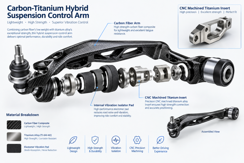
- Titanium (Ti-6Al-4V Grade 5): The ideal match for CFRP. Titanium has an anodic index close to carbon fiber, eliminating galvanic potential differentials and preventing interface corrosion without bulky coatings.
- Aluminum (7075-T6 / 6061-T6): Highly susceptible to severe galvanic pitting when joined to carbon. Assemblies require an insulating barrier layer, such as a co-cured non-conductive plain weave fiberglass (E-glass) scrim or hard-coat sulfuric anodization (MIL-A-8625 Type III).
- Precision Bushing Installation: Hardened stainless steel (17-4PH) and titanium hardpoint inserts require tight tolerancing (H7/g6 slips) to ensure anaerobic epoxy bonding layers maintain uniform bondline thickness (0.10–0.15 mm).
Our integrated precision CNC milling capabilities produce both composite chassis panels and companion titanium inserts in-house to guarantee micron-level joint fitment.
Machining Environment Controls: Spindle Sealing & Conductive Dust Mitigation
Carbon dust particles are electrically conductive and micron-sized. If left uncontrolled inside standard CNC machining enclosures, airborne composite particles infiltrate control cabinets, short-circuit motor drives, and cause severe mechanical wear on linear guideways.
Dry vs. Wet Composite Machining Dynamics
While flood coolant suppresses composite dust, wet composite machining introduces two major manufacturing risks for motorsport parts: moisture absorption into raw laminate cut edges (causing swelling and compromised cure adhesion) and the generation of hazardous sludge that is difficult to filter.
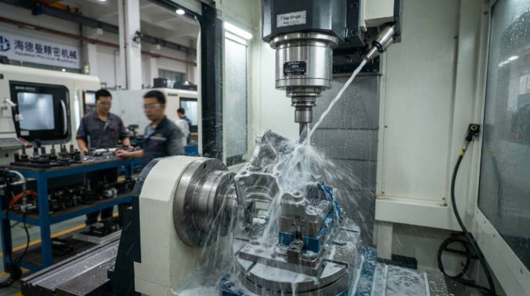
Tyneen uses dedicated dry-cutting composite machining centers equipped with positive-pressure hermetically sealed spindles (purged with 0.2 MPa dry compressed air) and ATEX-certified high-efficiency particulate air (HEPA) extraction hoods with face velocities exceeding 28 m/s.
Engineering Benchmarks: Speeds, Feeds, and Material Comparison Table
Machining feeds and speeds for carbon composite race components differ significantly from standard metal cutting parameters. High spindle RPM paired with controlled feed-per-tooth parameters prevents tool rubbing and fiber snagging.
| Material Grade | Specific Modulus (GPa/(g/cm³)) | Cutting Speed (SFM / m/min) | Chip Load (mm/tooth) | Recommended Tooling |
|---|---|---|---|---|
| Toray T300 / Epoxy (Autoclave) | 85.3 | 1,000–1,500 SFM (300–450 m/min) | 0.03–0.06 mm/z | CVD Diamond Burr / Diamond Router |
| Toray T800 / High-Tg Matrix | 105.7 | 1,200–1,800 SFM (360–550 m/min) | 0.02–0.05 mm/z | PCD Compression 2-Flute |
| Forged Carbon SMC (Vinylester) | 42.1 | 800–1,200 SFM (240–360 m/min) | 0.05–0.09 mm/z | Multi-Flute Diamond Burr (Cross-Cut) |
| 7075-T6 Aerospace Aluminum | 25.7 | 2,500–5,000 SFM (750–1500 m/min) | 0.10–0.25 mm/z | Uncoated High-Rake Polished Carbide |
| Ti-6Al-4V Grade 5 Titanium | 25.3 | 150–250 SFM (45–75 m/min) | 0.04–0.08 mm/z | AlTiN-Coated Variable Helix Carbide |
Quality Assurance & Metrology: CMM, Laser Scanning, and Ultrasonic NDT
Dimensional and structural verification is critical before any composite part is delivered to the pitlane. Machined composite components are certified under AS9100D and ISO 9001:2015 quality workflows.
Multi-Tier Inspection Protocol
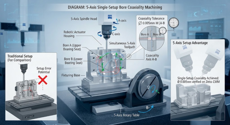
- Tactile CMM Inspection: Verifies hole center distances, bore concentricities, and chassis interface true positions within a volumetric accuracy of 1.8 µm + L/350.
- High-Definition 3D Optical Laser Scanning: Compares complex aerodynamic curvature against nominal 3D CAD models, generating whole-part color error deviation maps.
- Non-Destructive Ultrasonic Phased Array (NDT): High-frequency phased array testing detects hidden internal voids, matrix micro-cracking, or sub-surface ply delamination induced during aggressive machining passes.
Partner with Tyneen for On-Demand Custom Race Part Machining
Tyneen provides turnkey composite manufacturing solutions for top-tier motorsport teams, electric hypercar builders, and aerospace clients. From rapid turnaround on prepreg prototype splitters to scheduled production runs of titanium-hybrid chassis components, our facility delivers exceptional surface finishes and tight positional tolerances on every project.
Accelerate Your Track Development Program
Upload your CAD files, lay-up schedules, and GD&T drawings for direct DFM feedback and manufacturing lead times.
Frequently Asked Questions (FAQ)
What dimensional tolerances can be held on machined carbon fiber parts?
For autoclave-cured solid carbon laminates, Tyneen consistently holds profile edge tolerances of ±0.05 mm and precision drilled bore diameters to ±0.012 mm using PCD tooling and vacuum-assisted clamping systems.
Can you CNC machine wet layup carbon fiber components?
Yes, but wet layup laminates have lower fiber volume fractions and more internal voids than prepreg autoclave components. We modify feeds, speeds, and compression geometries to prevent frayed edges and matrix fracture.
Why do standard carbide tools wear out quickly in carbon fiber machining?
Individual carbon fibers have high micro-hardness and act as microscopic cutting edges against the tool. In uncoated carbide tools, this friction generates severe abrasive flank wear within minutes, causing fiber breakout rather than clean shearing.
How can motorsport teams reduce composite machining costs?
Machining costs can be reduced by standardizing internal corner radii to accommodate larger diameter PCD cutters (minimum 3.0 mm radius), consolidating multi-axis setups with unified datum references, and avoiding tight-tolerance holes in areas that do not serve as functional locating points.