Prototype to Mass Production: The Engineering Checklist
True manufacturing readiness requires an operational shift: moving away from chasing nominal dimensions on a digital CAD canvas toward managing statistical variance across continuous multi-axis machining operations. Without deliberate process controls, engineering teams face unexpected tool wear, cycle time bottlenecks, dimensional drift, and scrap rates exceeding 15% during early ramp phases.
Executing an effective prototype to mass production checklist requires rigorous geometric rationalization, strict metrology qualifications, and automated, multi-part workholding. This whitepaper details the technical framework required to transition complex mechanical components into high-volume manufacturing without sacrificing dimensional fidelity or engineering margins.
The 4-Pillar Production Readiness Framework: Redefining Mass Manufacturing Scalability
To determine if a prototype is truly ready for commercial volumes, production engineers evaluate designs through a structured 4-Pillar Scalability Matrix. This evaluation establishes clear engineering gates long before cutting production metal.
Process Capability (Cpk) measures how close a manufacturing process operates to its specification limits relative to natural process variability. A process with Cpk < 1.0 produces unacceptable statistical scrap, while Cpk ≥ 1.33 ensures fewer than 64 defective parts per million (PPM).
- 1. DFM Geometry & Feature Rationalization: Re-evaluating aspect ratios, deep internal radii, internal thread engagements, and non-critical linear tolerances to match high-feed, multi-axis machining dynamics.
- 2. Statistical Metrology & Quality Capability: Establishing measurement repeatability (Gage R&R < 10%), proving process capability indices (Cpk ≥ 1.33 for standard, Cpk ≥ 1.67 for critical dimensions), and establishing formal Production Part Approval Process (PPAP) controls.
- 3. Production Fixturing & Dedicated Automation: Replacing manual, multi-setup clamping with multi-sided horizontal tombstones, automated zero-point pneumatic systems, and dedicated robotic workcells.
- 4. Material Supply & Surface Integrity: Converting from expensive solid billet stock to near-net shapes, qualifying ASTM/AMS raw material integrity, and stabilizing batch chemical passivation and anodizing processes.
Phase 1: DFM & Geometric Tolerance Rationalization
During prototyping, mechanical designers often apply default title block tolerances of ±0.05 mm or specify tight ±0.005 mm limits across all interfaces. While functional for single-part development, these tight limits introduce unnecessary cost and cycle time into production runs.
High-volume manufacturing requires rationalizing every tolerance zone against its mating functional requirements. Shifting non-critical dimensions from ±0.005 mm to production-viable limits of ±0.020 mm or ISO 2768-m allows shops to switch from slow finishing passes to optimized dynamic milling paths using our precision CNC milling services.

- Internal Corner Radii: Maintain a cavity depth-to-tool radius ratio of ≤ 3:1. Avoid sharp 90° vertical corners that demand micro end mills or secondary sinker EDM steps; leave a radius of at least R = (Depth / 3) + 0.2 mm to prevent corner chatter and tool deflection.
- Thin-Wall Aspect Ratios: Keep unsupported wall height-to-thickness ratios below 4:1 for aluminum alloys and 3:1 for austenitic stainless steels. Thinner walls vibrate under aggressive spindle feeds, causing chatter marks that degrade surface finish beyond Ra 0.8 μm.
- Standard Hole Thread Depths: Thread engagement depths beyond 2× nominal diameter (2D) yield negligible pull-out strength gains in aluminum or steel, while significantly increasing the risk of broken taps during high-speed production runs.
Fc: Main cutting force (N), kc: Specific cutting force factor (N/mm²), b: Chip width (mm), h: Uncut chip thickness (mm). Reducing chip thickness via optimized corner radii directly limits tool deflection on thin features.
Material Selection & Stock Optimization: Billet vs Near-Net Shapes
In low-volume prototyping, hogging parts out of solid billet blocks makes sense to avoid up-front tooling investments. In contrast, running high volumes from solid billet creates poor buy-to-fly ratios, turning up to 80% of paid raw material into scrap chips.
For mid- to high-volume production, evaluating material stock forms is critical:
- Custom Extrusion Profiles: For consistent cross-sections in aluminum 6061-T6 or 6063, custom extruded profiles eliminate up to 60% of roughing cycle times and significantly cut raw stock mass.
- Cold-Heading and Die-Cast Blanks: High-volume structural brackets transition smoothly to high-pressure die casting (HPDC) or investment casting blanks, with high-tolerance datums and O-ring grooves subsequently finished via CNC machining.
- Material Certification Integrity: Ensure all incoming material meets certified standards. Require full Mill Test Reports (MTRs) compliant with ASTM International specs to verify yield strengths, grain direction, and chemical composition across our certified engineering materials inventory.
Phase 2: Quality Assurance & Statistical Process Validation (Cpk ≥ 1.33)
Proving quality for mass production requires moving past manual caliper checks. Instead, operations rely on continuous statistical control, disciplined Gage Repeatability & Reproducibility (Gage R&R), and formal PPAP packages.

- Gage R&R Stability: Measurement systems must consume less than 10% of the total tolerance band under variable operator testing. Gage R&R values between 10% and 30% require engineering review, while values over 30% are rejected.
- Process Capability Targets: Standard critical dimensions must maintain a Cpk ≥ 1.33 across an unbroken pilot batch of 30 to 100 parts. Flight-critical aerospace and medical components demand Cpk ≥ 1.67, confirming a defect probability below 1 part per billion.
- PPAP Level 3 Documentation: Deliver complete Production Part Approval Process folders, including Design Records, Process Flow Diagrams, Process Failure Mode and Effects Analysis (PFMEA), Control Plans, and formal Part Submission Warrants (PSW).
- AS9102 First Article Inspection (FAI): Balloon every drawing characteristic, measuring 100% of dimensions across three randomly selected initial parts to confirm machine tool kinematic accuracy.
USL: Upper Specification Limit, LSL: Lower Specification Limit, μ: Process Mean, σ: Standard Deviation (Estimated). Process centering and tight variance dictate production yield.
Metrology Infrastructure: Automated CMM Scanning & In-Line Inspection
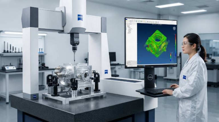
Relying on manual surface plates creates inspection backlogs that can stall high-speed spindle operations. Mass production lines resolve this by pairing in-spindle optical probes with automated Coordinate Measuring Machines (CMM).
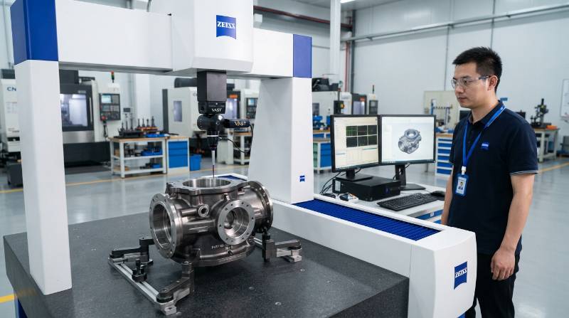
- Automated Multisensor CMM Routines: Zeiss PRISMO and CONTURA bridge CMM systems deliver sub-micron length measurement errors (E0,MPE down to 0.9 + L/350 μm), mapping Geometric Dimensioning and Tolerancing (GD&T) true position callouts instantly.
- High-Resolution Surface Profilometry: Quantitative surface roughness verification using MarSurf contact profilometers ensures critical seal interfaces meet Ra 0.4 μm to Ra 0.8 μm targets without manual polishing.
- In-Line Renishaw Tool & Part Probing: Machine-mounted optical probes confirm part datum locations and detect broken tools in-cycle, preventing non-conforming parts before an entire pallet finishes machining.
Phase 3: Production Fixturing, Tooling Amortization & Machining Scaling
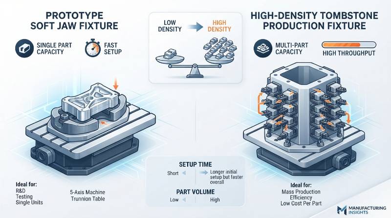
A primary bottleneck when scaling hardware is fixture setup time. Prototype components typically rely on soft jaws in three-axis CNC vises, requiring operators to manually cycle, flip, and re-clamp the stock across three to five separate operations.
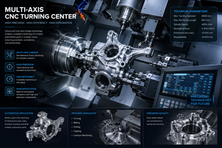
To scale efficiently, operations transition to advanced multi-axis machining workcells. Running parts on horizontal machining centers (HMC) or multi-pallet 5-axis platforms allows multiple workpieces to be clamped onto four-sided pneumatic tombstones, drastically cutting handling times.
- Zero-Point Clamping Systems: Quick-change zero-point pneumatic plates allow offline part loading while the spindle cuts, keeping spindle utilization rates above 85%.
- Eliminating Setup Stacking Error: 5-axis single-setup machining completes 5-sided milling and multi-angle drilling without re-clamping, eliminating the setup-to-setup stack-up errors that cause true position drift.
- Custom Solid Carbide Form Tools: Replacing multiple standard end mills with custom-ground form cutters combines chamfering, radius profiling, and port contouring into a single toolpath pass.
High-Volume Turning & Swiss Mill-Turn Scalability
For cylindrical shafts, micro-pins, threaded couplings, and fluid fittings under 38 mm diameter, standard multi-axis chucking centers are often too slow. These parts run more efficiently on high-precision Swiss-type mill-turn centers.
By leveraging high-volume CNC turning and Swiss machining with bar feeders, sliding headstocks, and synchronized sub-spindles, parts drop off the machine complete. This eliminates secondary handling, maintains runout tolerances under 0.005 mm, and drops individual part cycle times from minutes to seconds.
Phase 4: Supply Chain, Secondary Operations & Total Landed Cost (TLC)
Machining efficiency accounts for only part of the final unit economics. Secondary finishes and multi-tiered logistics often drive hidden costs and introduce scrap risks if not tightly managed.
Calculating the true production cost requires an evaluation of the Economic Order Quantity (EOQ):
D: Annual demand quantity, S: Fixed setup and programming cost per run, H: Holding/carrying cost per unit per year. Balancing batch size against inventory holding costs optimizes unit economics.
Critical post-processing variables include:
- Chemical Passivation & Plating: Specify passivation per ASTM A967 (Citric vs Nitric acid formulations) for surgical stainless steels to ensure complete surface free-iron removal without etching high-tolerance features.
- Anodizing Layer Growth: Account for coating thickness variations early. Type II anodizing adds roughly 10 μm to 15 μm, while Type III Hardcoat adds 25 μm to 50 μm (with 50% penetration and 50% outward build-up). Precision bore and thread callouts must state dimensions “before plating” or specify custom masking.
- Process Substitution for Scale: When annual production volumes exceed 20,000 units, consider shifting non-critical prismatic elements to hybrid routes like our precision stamping and casting solutions, reserving 5-axis CNC machining strictly for critical datums and interfaces.
The Benchmark Scaling Case: High-Mix Titanium and Aerospace 7075-T6 Production
An autonomous aerospace robotics client approached Tyneen to scale a complex avionics chassis manifold. The part featured complex multi-port intersecting fluid channels, 42 threaded blind holes, and tight datum location callouts of ±0.005 mm across an envelope of 280 × 210 × 95 mm.
During their initial prototyping phase with a local machine shop, the client saw scrap rates climb past 32%. This was driven by thermal expansion drift, tool deflection in deep cavity corners, and bore misalignments caused by manual re-clamping across four distinct 3-axis setups.
| Production Parameter | Client R&D Prototype Approach | Tyneen Production Scaled Cell |
|---|---|---|
| Machine Configuration | 3-Axis VMC (4 manual setups, soft jaws) | 5-Axis DMG MORI (Single setup, zero-point chucking) |
| Thermal Drift Management | Ambient factory floor (±8°C daily shift) | Spindle chilling, through-tool coolant & 20°C cleanroom metrology |
| Total Machining Cycle Time | 142 minutes per part | 46 minutes per part (67.6% reduction) |
| Statistical Capability (Cpk) | Cpk = 0.81 (Unstable; high rework rate) | Cpk = 1.72 (Demonstrated over 5,000 units) |
| Scrap / Yield Rate | 68% yield rate (32% scrap/rework) | 99.6% first-pass yield rate |
Tyneen’s application engineering team updated the process routing:
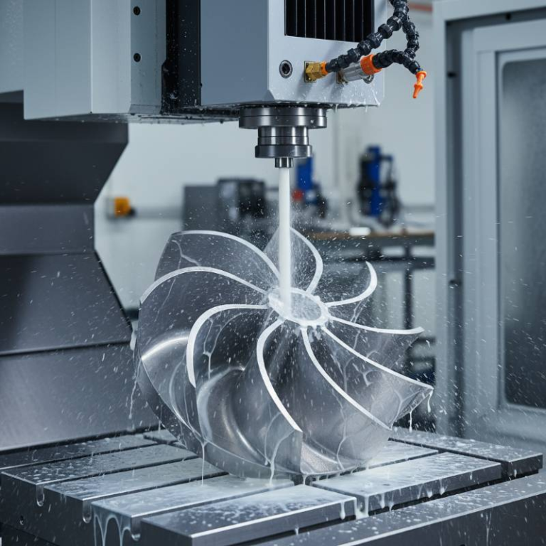
- Consolidated all machining paths into a single setup using a high-precision 5-axis DMG MORI machining center with high-pressure through-spindle coolant (70 bar) to evacuate chips from deep cavities.
- Installed dynamic tool-wear probing routines that update controller diameter offsets every 12 cycles, offsetting micro-flank tool wear.
- Shifted finish-inspection to an automated Zeiss PRISMO CMM cell, ensuring that each 500-piece shipping lot included full statistical data proving datum true positions remained within ⌀0.008 mm.
Tyneen Industrial Capabilities: Metrology-Driven Manufacturing from Prototype to High Volume
Tyneen operates as an integrated contract manufacturing partner, purpose-built to transition complex prototypes into production-scale volumes without handoff delays or quality drop-offs.
- Industry-Standard Certifications: Fully audited quality management systems compliant with ISO 9001:2015, IATF 16949 (Automotive), and AS9100D (Aerospace and Defense).
- Precision Machining Fleet: Advanced 3-axis, 4-axis, and simultaneous 5-axis machining centers from DMG MORI, Hermle, and Mazak, paired with multi-axis Citizen Swiss mill-turn lathes.
- Climate-Controlled Metrology Cleanrooms: In-house inspection facilities holding 20°C ± 0.5°C environments, equipped with automated contact and optical scanning Zeiss CMMs, Keyence digital comparators, and calibrated MarSurf surface roughness gages.
- Fast-Turn DFM Feedback: Experienced manufacturing engineers review production packages, providing actionable DFM feedback and transparent quote breakdowns within 2 hours.
Deep Engineering Trade-offs: Process Substitution and Quality Verification Matrices
Choosing the right production method requires balancing tooling amortization, cycle speed, and geometry constraints across projected annual production runs.
| Process Parameter | Precision CNC Machining | High-Pressure Die Casting (HPDC) | Metal Injection Molding (MIM) |
|---|---|---|---|
| Economic Volume Break-Even | 1 to 10,000 units | > 5,000 units | > 20,000 units |
| Upfront Tooling Capital (NRE) | Low (500 –3,000 fixtures) | High (25,000 –80,000 dies) | Very High (15,000 –50,000 molds) |
| Linear Tolerance Capability | ±0.005 mm to ±0.020 mm | ±0.100 mm to ±0.250 mm | ±0.050 mm (±0.3% to ±0.5%) |
| Surface Roughness (Ra) | Ra 0.4 μm – Ra 1.6 μm | Ra 1.6 μm – Ra 3.2 μm | Ra 0.8 μm – Ra 1.6 μm |
| Material Versatility | Virtually unlimited metals/polymers | Aluminum, Zinc, Magnesium alloys | Select Stainless, Steels, Titanium |
| Design Flexibility / Changes | Immediate (via CAM updates) | Extremely costly tool rework | Costly mold rework |
Raw Material Verification and Counterfeit Alloy Mitigation
Material traceability risks increase during high-volume purchasing runs. Substandard or counterfeit bar stock can lead to unexpected tool wear, internal porosity, and field failures.
- X-Ray Fluorescence (XRF) Spectrometry: Incoming materials undergo Positive Material Identification (PMI) using handheld XRF analyzers to confirm elemental composition against ASTM specifications before stock hits the saws.
- Lot-Controlled Traceability: All incoming lots are tracked back to original mill heat numbers, backed by physical and chemical Mill Test Reports (MTRs) compliant with EN 10204 Type 3.1 standards.
- Ultrasonic Flaw Inspection: High-stress aerospace structural forgings and thick plate stock undergo ultrasonic testing per AMS 2630 standards to detect subsurface voids, inclusions, and porosity.
Interactive Production Readiness Sign-Off Matrix
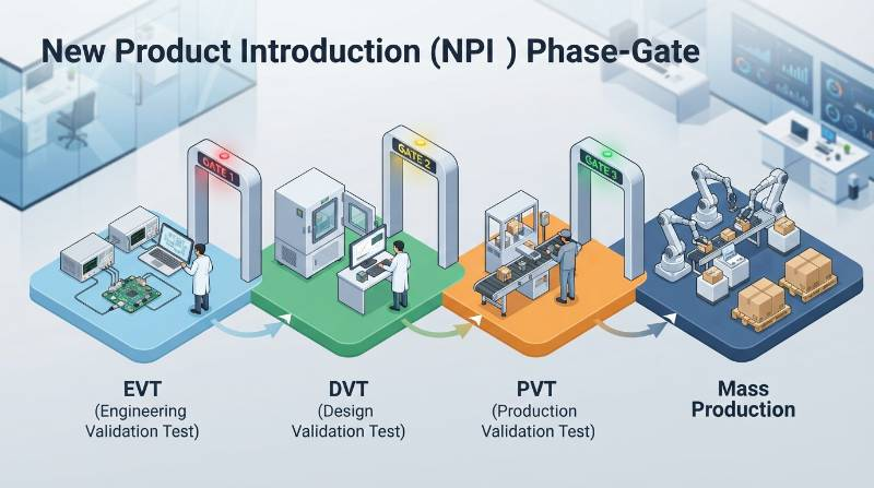
Engineering leaders should use this structured sign-off checklist across each hardware phase-gate milestone before releasing production funds:
| NPI Phase Gate | Key Engineering Criteria | Required Verification Deliverable | Sign-Off Status |
|---|---|---|---|
| EVT (Engineering Validation) | Functional proof of concept; critical geometric feasibility confirmed. | Initial DFM evaluation report; preliminary 3D STEP models with base datums. | Gate Closed [ ] |
| DVT (Design Validation) | Fit, finish, and assembly verification; preliminary cycle time targets established. | Fully ballooned 2D prints; Gage R&R study (<10%); baseline FAI inspection report. | Gate Closed [ ] |
| PVT (Production Validation) | Pilot run on production tooling at production speeds; capacity verified. | Pilot batch capability study (Cpk ≥ 1.33); PPAP Level 3 package submittal; PFMEA review. | Gate Closed [ ] |
| Mass Production (SOP) | Continuous high-volume production with stable statistical yields. | Approved Part Submission Warrant (PSW); active in-line SPC charting; packing/shipping release. | Release Approved [ ] |
The 3-Step Production Bridge: Streamlined Transition Protocol to Mass Production
To eliminate schedule delays, production ramps should follow a clear, linear path from final engineering sign-off to volume delivery.
Your Path to Production Scale with Tyneen
- Step 1: Upload Complete Engineering Package: Submit your 3D STEP/IGES files alongside ballooned 2D PDF prints with explicit GD&T callouts, surface finish values, and expected annual volumes (EAU).
- Step 2: Receive Detailed DFM Analysis & Quote in 2 Hours: Tyneen’s production engineers analyze tool accessibility, propose tolerance adjustments to lower costs, and provide transparent, tiered-volume quotes.
- Step 3: Fast-Turn Pilot Run & Global Delivery: Approve a production-tooled pilot batch with full AS9102 First Article Inspection reports, Zeiss CMM verification, and material test certs before greenlighting volume runs.
Frequently Asked Questions (FAQ)
What is the primary difference between prototyping and mass production CNC machining?
Prototyping focuses on geometric verification, fit, and rapid turnaround for single units, typically using universal soft-jaw vise fixtures and manual setup compensation. Mass production CNC machining prioritizes statistical repeatability (Cpk ≥ 1.33), minimal cycle times, multi-part automated fixturing (such as horizontal tombstones), and predictive tool-wear tracking to ensure uniform quality across thousands of parts.
What specific documentation is included in a PPAP Level 3 package?
A PPAP Level 3 submission is the standard package for automotive, industrial, and aerospace hardware. It includes 100% ballooned Part Inspection Results, Design Records, approved Engineering Change Documents, Process Flow Diagrams, Process FMEA (PFMEA), Control Plans, Measurement System Analysis (Gage R&R < 10%), Initial Process Studies (Cpk/Ppk data), certified Material Test Reports (MTRs), and a signed Part Submission Warrant (PSW).
How do internal corner radiuses directly impact mass production machining costs?
Sharp internal vertical corners or radii smaller than one-third of the cavity depth force machines to decelerate to prevent corner chatter and tool breakage. They also necessitate tiny end mills that run at significantly slower feed rates. Designing internal radii to at least R = (Depth / 3) + 0.2 mm allows larger, stiffer roughing tools to clear material efficiently, reducing overall machining cycle times by up to 30%.
Why is a Cpk of 1.33 considered the minimum acceptable baseline for volume manufacturing?
A Cpk of 1.33 represents a 4-sigma statistical process capability, indicating that the natural variation of the process consumes no more than 75% of the total allowable tolerance band. Statistically, this limits the defect rate to approximately 63 parts per million (PPM). For flight-critical aerospace or life-critical medical devices, this standard is elevated to Cpk ≥ 1.67 (5-sigma), which restricts theoretical defects to under 1 PPM.