Mastering DFM for CNC Milling: Reduce Machining Costs
The Fundamentals of DFM for CNC Milling
Design for Manufacturability (DFM) is the bridge between a theoretical CAD model and a cost-effective physical part. In the competitive landscape of 2026, DFM for CNC milling is no longer an optional check; it is a financial imperative.
At Tyneen, we see how early design decisions dictate 70% to 80% of the final manufacturing cost. Value engineering CNC components requires a deep understanding of subtractive limitations to prevent over-expenditure on “un-machinable” features.
The Precision-to-Profit Framework: Our Proprietary DFM Protocol
Effective CNC cost optimization requires a structured approach. We utilize the Precision-to-Profit Framework, a three-step methodology designed to maximize manufacturing velocity while maintaining strict quality benchmarks.
This framework prioritizes geometric simplification, tool-access optimization, and material-specific feed rates. By aligning design intent with the physical realities of High-Speed Machining (HSM), we ensure that every cut adds value rather than just cost.
“Efficiency in CNC starts at the CAD level. If you design for the tool rather than just the intent, you eliminate 80% of manufacturing friction.” — Marcus V., Senior Manufacturing Engineer.
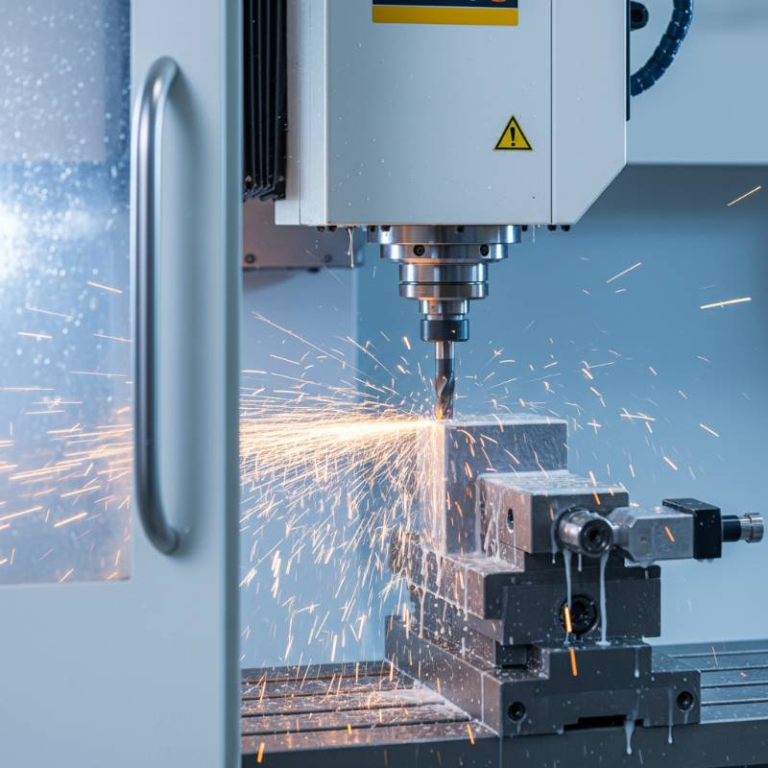
Geometry Optimization: Physics of the End Mill
The most common cost driver in CNC milling is ignoring the physical constraints of the cutting tool. Standard end mills are cylindrical and rotate; they cannot create perfectly square internal corners.
The Problem with Sharp Corners
Forcing a machine to create sharp internal corners often requires expensive Electrical Discharge Machining (EDM). Instead, design internal corners with a radius slightly larger than the tool radius. This allows the tool to navigate the corner without a full stop, maintaining constant chip load and preventing tool breakage.
Pocket Depth-to-Width Ratios
Deep cavities require long tools, which are prone to deflection and vibration (chatter). Our data shows that reducing pocket depth-to-width ratios from 5:1 to 3:1 can save 20% in machine time. Deep pockets necessitate slower feed rates and multiple passes, significantly increasing the price per part.
Tolerance Strategy and ASME Y14.5 Standards
Over-engineering is a silent profit killer. Assigning a ±0.001″ tolerance to a non-mating surface forces the machinist to use slower processes and more frequent inspections.
We advocate for the ASME Y14.5 GD&T standard to define functional requirements accurately. By using Geometric Dimensioning and Tolerancing, you communicate exactly where precision matters, allowing for looser machining tolerances on secondary features.
| Tolerance Range | Cost Multiplier | Typical Process |
|---|---|---|
| ±0.005″ (Standard) | 1.0x | Standard Milling |
| ±0.001″ (Tight) | 1.5x – 2.0x | Precision Finishing |
| ±0.0002″ (Ultra) | 3.0x+ | Grinding/Honing |
Reducing Setups and 3-Axis vs. 5-Axis Cost Analysis
Every time a machinist has to touch the part to flip or rotate it, costs rise. Setup time reduction is the fastest way to lower the unit price of complex parts. Eliminating just one re-fixturing step can reduce total part cost by 15%.
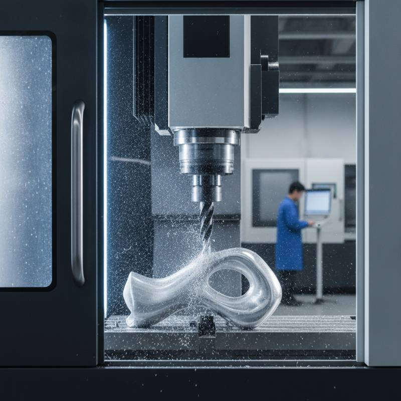
3-Axis vs. 5-Axis Efficiency
While 5-axis machines have a higher hourly rate, they often eliminate the need for multiple workholding solutions and custom jigs. For complex geometries, 5-axis milling can be more economical because it completes the part in a “single hit.”
Explore our full range of CNC Machining Services to determine which platform fits your production volume.
AI Prompt Engineering for DFM Optimization
In 2026, AI is a standard tool for auditing CAD files before they reach the shop floor. Engineers can use Large Language Models (LLMs) to perform rapid DFM sanity checks on their designs.
Try using this prompt with your engineering AI: “Review this STEP file metadata for CNC milling. Identify any internal radii smaller than 3mm or pockets deeper than 30mm. Suggest more machinable standard tool sizes to reduce cycle time.”
Sustainability and Material Sovereignty
Material waste is both an environmental and financial burden. By optimizing part nesting and choosing stock sizes that minimize chips, you reduce your carbon footprint and material spend. Refer to our Material Selection Guide for high-machinability, sustainable alternatives.
Furthermore, protecting your IP is critical. We maintain ISO 27001 and TISAX compliance to ensure your proprietary designs remain secure throughout the procurement lifecycle.
2026 CNC Cost-Reduction Checklist & Assessment
Before finalizing your design, run through this self-check to ensure maximum ROI:
- Are all internal radii at least 10% larger than a standard end mill?
- Can the part be machined in 2 or fewer setups?
- Are surface finish requirements realistic for the application?
- Is the wall thickness greater than 0.8mm for metals?
Get Your Free DFM Assessment
Upload your drawings to our Instant Quoting Engine today for a detailed engineering review and cost breakdown.
Frequently Asked Questions about CNC DFM
What are standard drill diameters for CNC?
Using standard fractional or metric drill sizes (e.g., 1/8″, 1/4″, 6mm) avoids the need for custom tooling or slower circular interpolation with an end mill.
How does surface roughness impact cost?
An “as-machined” finish (3.2 μm Ra) is the most economical. Requiring a 0.8 μm Ra finish adds secondary operations and can increase costs by 20% to 40%.