CNC Machining Tolerances: Limits, Standards & Costs
The Precision Engineering Framework: Evaluating Machinability vs. Cost-Inflation Risk
In mechanical design, specifying a tolerance is fundamentally an economic decision. Every micron of unnecessary precision compounds manufacturing costs, tool wear, and scrap risk exponentially.
Engineering teams often default to overly restrictive bilateral tolerances to mitigate assembly failures. However, this practice shifts risk downstream into machining cycles, inspection overhead, and yield loss.
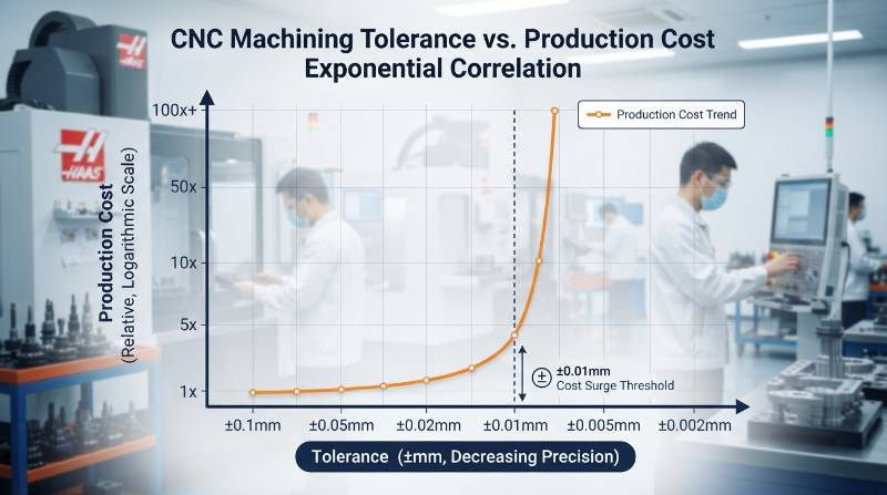
An effective evaluation framework balances functional performance against production feasibility across four key engineering vectors:
- Kinematic Requirement: Differentiating dynamic sliding interfaces (requiring tight fits) from static mounting clearances.
- Material Rigidity: Balancing cutting forces against raw stock deflection and thermal expansion coefficients.
- Feature Topology: Accounting for deep internal pockets, thin web walls, and high aspect ratios that induce tool vibration.
- Metrology Capability: Ensuring inspection instruments possess gauge repeatability and reproducibility (GR&R) ten times higher than the specified tolerance.
A transition from ±0.1 mm to ±0.005 mm typically yields a 250% to 400% surge in overall part COQ.
Machining Tolerance Classifications & Global Standards (ISO 2768, ISO 286, ASME Y14.5)
Global manufacturing relies on standardized tolerance classes to ensure functional interchangeability. The most widely referenced standards are ISO 2768 for general linear/angular tolerances and ASME Y14.5 for geometric dimensioning.
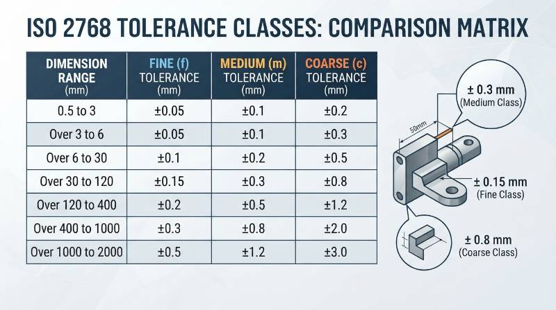
| Tolerance Class | 0.5 to 3 mm | >3 to 6 mm | >6 to 30 mm | >30 to 120 mm | >120 to 400 mm |
|---|---|---|---|---|---|
| f (Fine) | ±0.05 | ±0.05 | ±0.1 | ±0.15 | ±0.2 |
| m (Medium) | ±0.1 | ±0.1 | ±0.2 | ±0.3 | ±0.5 |
| c (Coarse) | ±0.2 | ±0.3 | ±0.5 | ±0.8 | ±1.2 |
| v (Very Coarse) | — | ±0.5 | ±1.0 | ±1.5 | ±2.5 |
Standard Commercial Tolerances (ISO 2768-m / ±0.1 mm to ±0.2 mm)
Commercial-grade CNC machining operates primarily within ISO 2768-m parameters (±0.1 mm to ±0.2 mm for small-to-medium features).
This class enables high feed rates, aggressive roughing cycles, and standardized workholding without specialized vibration dampening. It is ideal for structural brackets, non-critical housings, and general machinery frames.
High-Precision Tolerances (ISO 2768-f / ±0.01 mm to ±0.05 mm)
Achieving ISO 2768-f and precision limits (±0.01 mm to ±0.05 mm) requires rigid machine tools, precise spindle runout control (<1 μm), and constant tool wear offset tracking.
Engineers deploying custom CNC milling solutions rely on this tolerance level for bearing bores, dowel pin alignments, and matched mating surfaces.
Ultra-Precision Sub-Micron Capabilities (±0.001 mm to ±0.005 mm)
Ultra-precision operations span limits between ±0.001 mm and ±0.005 mm (±0.00004 in to ±0.0002 in). These bounds are mandatory for aerospace hydraulic spools, fuel injector orifices, and optical alignment fixtures.
Executing these specifications requires advanced CNC machining services equipped with direct-drive linear motors, diamond tooling, glass scale position encoders, and fully temperature-stabilized cutting fluids.
Geometric Dimensioning & Tolerancing (GD&T) vs Linear Dimensions
Traditional coordinate plus/minus tolerancing creates square or rectangular tolerance zones. This approach fails to control form, orientation, and location relationships effectively.
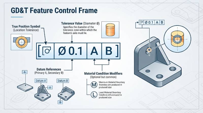
GD&T (ASME Y14.5 / ISO 1101) establishes cylindrical and uniform boundary zones, expanding usable manufacturing allowances while guaranteeing assembly function.
| Geometric Characteristic | Standard Capability | Precision Capability | Ultra-Precision (Tyneen Benchmark) |
|---|---|---|---|
| True Position (⌀) | ⌀0.05 mm | ⌀0.02 mm | ⌀0.008 mm |
| Flatness / Parallelism | 0.05 mm / 100 mm | 0.015 mm / 100 mm | 0.003 mm / 100 mm |
| Cylindricity / Roundness | 0.02 mm | 0.008 mm | 0.002 mm |
| Total Runout | 0.03 mm | 0.01 mm | 0.003 mm |
True position tolerances are especially valuable for multi-hole patterns on mating flanges. When calculated under Maximum Material Condition (MMC), they provide bonus tolerance as feature sizes deviate from minimum material limits, preventing false part rejections.
Material-Specific Achievable Tolerances & Thermal Expansion Dynamics
Achievable precision depends heavily on workpiece material properties. Modulus of elasticity, internal residual stress, and thermal expansion govern dimensional stability during and after material removal.
Selecting optimized precision engineering materials requires evaluating how workpiece temperature shifts alter final part geometry.
ΔL = Dimensional change (mm), L₀ = Nominal length (mm), α = Coefficient of Thermal Expansion (10⁻⁶/K), ΔT = Temperature differential relative to 20°C standard (K).
For an Al 6061-T6 part with a nominal length of 200 mm machined at 28°C (shop ambient) and measured at standard 20°C (ΔT = -8 K):
A 37 μm thermal shift completely consumes a ±0.02 mm tolerance window unless thermal compensation is applied during the cutting cycle.
Metals: Aluminum, Stainless Steel, Titanium, and Inconel
- Al 6061-T6 / Al 7075-T6: Excellent machinability and chip evacuation. High CTE (23.1 × 10⁻⁶/K) requires tight coolant temperature control during high-speed finishing.
- Stainless Steel 304 / 316L: Low thermal conductivity and work-hardening tendencies generate cutting heat. Feeds must stay aggressive to prevent surface glazing. Achievable tolerance: ±0.01 mm.
- Titanium Ti-6Al-4V (Grade 5): Low elastic modulus (114 GPa) creates workpiece spring-back under cutting tool pressure. Requires sharp geometry and rigid clamping to maintain ±0.005 mm limits.
- Inconel 718: Extreme shear strength and abrasive carbide inclusions accelerate tool notch wear, demanding in-process touch-probing to offset tool degradation.
Engineering Plastics: PEEK, Delrin (POM-C), PTFE, and Nylon
Polymers feature thermal expansion coefficients up to 10 times higher than metals, lower elastic moduli, and susceptibility to hygroscopic expansion.
- PEEK (Unfilled / 30% Carbon Filled): High dimensional stability. Annealing between roughing and finishing passes is mandatory to relieve internal stresses and hold ±0.015 mm tolerances.
- Delrin (Acetal POM-C): Free-machining with low moisture absorption. Susceptible to center-line porosity in thick cross-sections, requiring balanced roughing cuts.
- Nylon (PA6 / PA66): Highly hygroscopic. Ambient humidity changes can expand dimensions by up to 0.2% post-machining. Typical holding tolerance: ±0.05 mm to ±0.1 mm.
- PTFE (Teflon): High ductility and continuous creep under clamping loads make holding limits tighter than ±0.05 mm unfeasible without cryogenic chilling.
Post-Surface Treatment Dimensional Allowance Calculations
Surface finishing processes alter final part dimensions through chemical deposition, layer conversion, or micro-etching. Tolerances on 2D drawings must specify whether values apply before or after surface treatment.
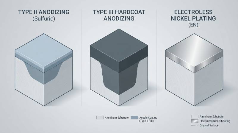
| Surface Treatment | Total Layer Thickness | Dimensional Growth per Surface | Pre-Machining Sizing Strategy |
|---|---|---|---|
| Type II Anodizing (Sulfuric) | 10 to 25 μm | +5 to +12.5 μm (50% penetration / 50% buildup) | Undersize OD / Oversize ID by ≈10 μm per side |
| Type III Hardcoat Anodizing | 40 to 60 μm | +20 to +30 μm (50% penetration / 50% buildup) | Pre-cut bores larger by 40 to 50 μm on diameter |
| Electroless Nickel Plating (ENP) | 5 to 25 μm | +5 to +25 μm (100% surface deposition) | Account for uniform 2× thickness change across total diameter |
| Passivation (ASTM A967) | <0.005 μm (Oxide) | 0.00 μm (Negligible) | Machine to exact print nominal |
Multi-Axis Kinematics: 3-Axis VMC vs 5-Axis Centers vs Swiss Lathes
Machine tool kinematics determine geometric capability and setup repeatability. Moving a workpiece across multiple fixtures introduces cumulative stack-up errors that often exceed precision boundaries.
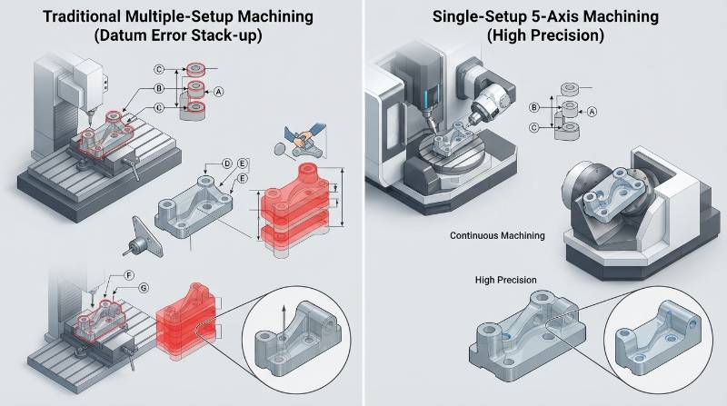
Single-setup machining delivers distinct tolerance advantages across different machine configurations:
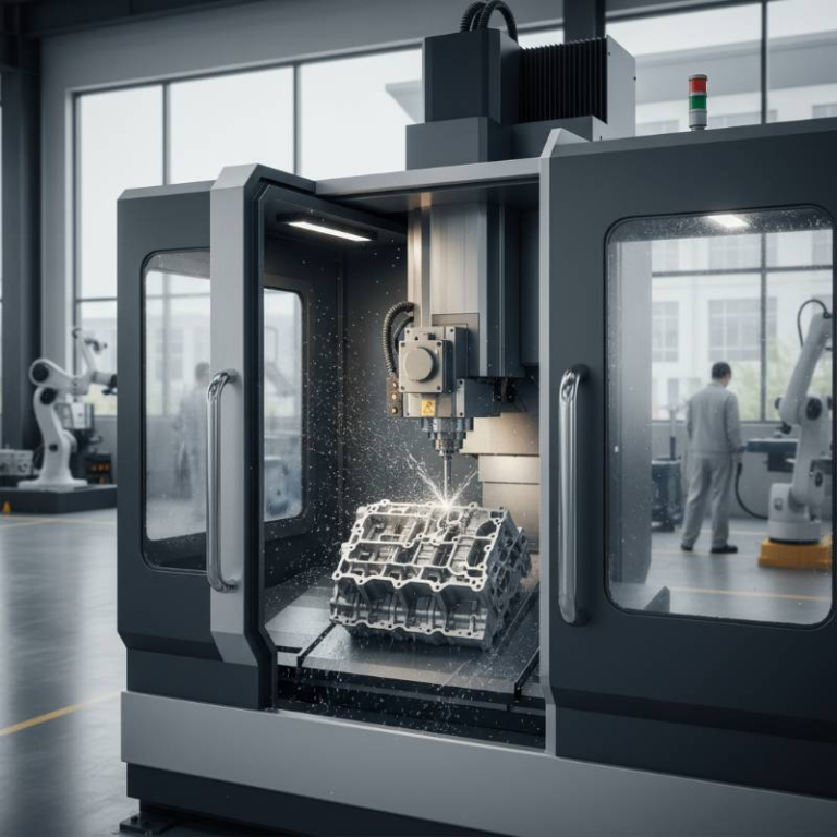
- 3-Axis Vertical Machining Centers (VMC): Highly rigid for planar profiling. Complex multi-sided parts require 2 to 4 reclamping setups, introducing fixture location errors of ±0.015 mm to ±0.03 mm per operation.
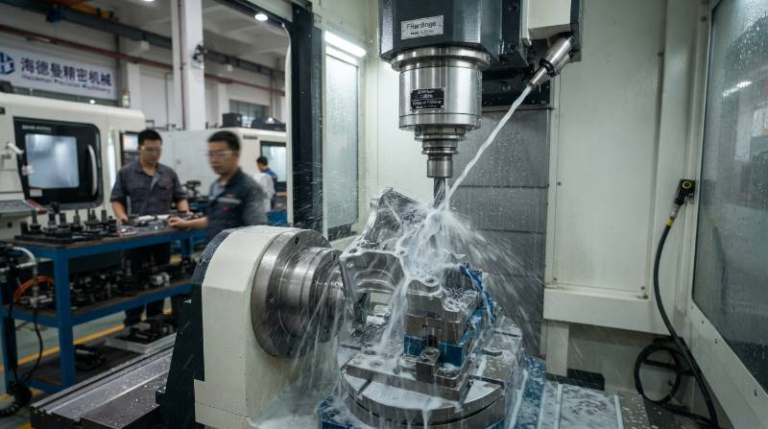
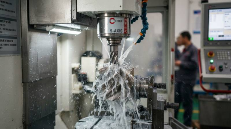
- 5-Axis Simultaneous Machining Centers: Completes 5-sided prismatic operations in a single workholding setup. Eliminates datum transfer stack-up, holding true positions within ⌀0.008 mm and perpendicularity within 0.005 mm across distinct coordinate planes.
- Swiss-Type Turning Centers: Workpieces are supported directly at the guide bushing near the cutting tool. This setup eliminates part deflection on long, slender components (L/D ratios > 20:1), enabling high-precision CNC turning with runouts below ±0.002 mm.
The Tyneen Closed-Loop Tolerance Verification Protocol (CLTV-P)
To eliminate scrap and ensure zero-defect production for critical hardware, Tyneen implements a proprietary 5-stage manufacturing and verification system:
- Thermal Baseline & DFM Review: Every 3D CAD/STEP model is analyzed for cutting tool access, stress concentration pockets, and thermal drift factors before CAM post-processing.
- In-Process Renishaw Probing: Workpieces and cutting tools undergo automated in-spindle laser probing to dynamically update work datum shifts and tool-wear offsets inside the CNC controller.
- Stage-Separated Stress Relief: Critical geometries undergo heavy roughing, dwell cycles, and finishing passes separated by thermal stabilization windows to relieve internal alloy stresses.
- 20°C Climate-Controlled Metrology: Finished components undergo a mandatory 4-hour thermal equilibrium soak in our metrology lab before final inspection on Zeiss Coordinate Measuring Machines (CMM).
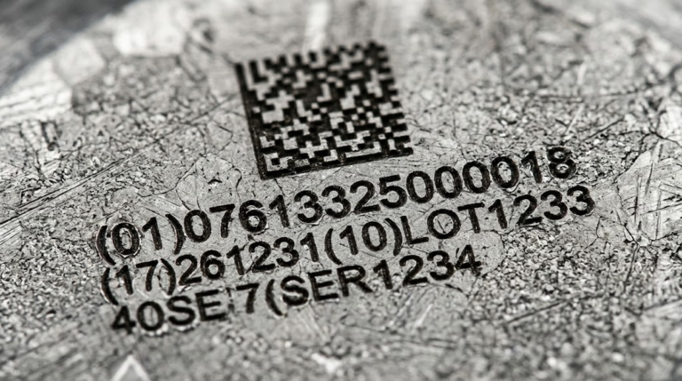
- Digital Traceability & Archival: AS9102 First Article Inspection (FAI) reports, Raw Material Mill Test Reports (MTR), and complete CMM point-cloud data are securely archived for full traceability.
Extreme Niche Benchmark: Multi-Axis Aerospace Titanium & Medical Manifold Machining
Ultra-precision manufacturing is proven in complex geometry machining under extreme material constraints. A representative benchmark demonstrates this capability clearly:
Component Profile: Aerospace Sensor Chassis & Integrated Fluidic Manifold
Material: Titanium Ti-6Al-4V (Grade 5)
Wall Thickness: 0.60 mm uniform web sections
Critical Callouts: Bore diameter ⌀12.000 mm (+0.005 / -0.000 mm), Cylindrical True Position within ⌀0.008 mm relative to Datum A/B/C, Ra 0.4 μm internal surface finish without post-machining distortion.
Standard 3-axis operations fail on this geometry because clamping pressures distort the 0.60 mm thin walls, and cutting heat induces severe warpage. Tyneen’s production methodology addressed these issues systematically:
- Custom Hydrostatic Fixturing: Custom multi-point vacuum and hydrostatic conformal chucks eliminated localized mechanical clamping deflection.
- 5-Axis Trochoidal Toolpaths: High-speed adaptive clearing maintained constant radial tool engagement and low cutting forces, directing heat into the chips rather than the thin titanium walls.
- Diamond-Coated Micro-Endmills: Finish passes executed at 18,000 RPM using high-pressure through-spindle coolant maintained a Ra 0.32 μm finish and held bore roundness within 0.0025 mm.
Tyneen’s Quality Assurance: ISO 9001, IATF 16949 & Zeiss Metrology Capabilities
Our quality management system is certified to ISO 9001:2015 and IATF 16949 standards, providing validated inspection processes for precision-critical industries.
Our metrology facility operates at a continuous 20°C (±0.5°C) and 45% relative humidity to eliminate environmental inspection errors.
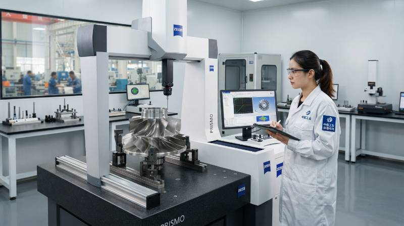
Our internal inspection equipment includes:
- Zeiss Prismo CMM: Volumetric length measurement error (E₀) as low as 0.9 + L/350 μm, equipped with continuous dynamic scanning heads.
- Keyence IM-8000 Optical Comparators: Sub-micron automated 2D field-of-view dimensional measurement.
- Taylor Hobson Form Talysurf: Contact surface profilometry resolving surface roughness down to Ra 0.01 μm.
- XRF Material Analyzers: Positive Material Identification (PMI) verifying chemical alloy compositions prior to production setup.
Comprehensive Technical FAQ & Verification Protocols for Ultra-Tight Tolerances
What is the relationship between surface roughness (Ra) and dimensional tolerance?
Surface roughness and dimensional tolerance are mechanically linked. A part cannot maintain a ±0.005 mm (5 μm) dimensional tolerance if its surface roughness peaks and valleys (Rz) exceed that window.
Achieving ±0.005 mm typically requires a surface finish of Ra ≤ 0.4 μm (16 μin). Standard commercial tolerances of ±0.1 mm pair naturally with standard as-machined finishes of Ra 1.6 μm to 3.2 μm (63–125 μin).
At what temperature are CNC machining drawing dimensions legally verified?
Under international metrology standards (ISO 1 / ASME Y14.5), all drawing dimensions and tolerances apply strictly at a standard reference temperature of 20°C (68°F).
Measurements taken on shop floors at elevated temperatures must be mathematically adjusted using the material’s linear CTE to determine acceptance or rejection.
How do ISO 286 shaft and hole fit classes correlate to CNC machining operations?
ISO 286 defines standard limits and fits for mating cylindrical features. Common classes include:
- H7/g6 (Locational Clearance Fit): Free assembly with minimal radial play; requires precision bore reaming (H7: +0.015/-0.000 mm for ⌀18 mm).
- H7/k6 (Transition Fit): True location without perceptible clearance; used for rigid bearing journals.
- H7/p6 (Interference / Press Fit): Permanent mechanical assembly requiring hydraulic press-fitting or thermal shrink-fitting.
Streamlined 3-Step Precision Manufacturing Pathway: CAD to Verified Part
Transitioning from complex CAD engineering models to verified, production-ready hardware follows a direct 3-step workflow:
Precision Onboarding Process
- Upload 3D CAD & 2D Drawings: Submit your 3D models (STEP/IGES) alongside 2D PDF drawings detailing critical GD&T feature frames, fit classes, and surface finish callouts.
- Automated DFM & Quote in 2 Hours: Receive comprehensive manufacturability feedback, tooling optimization recommendations, and pricing directly from our engineering team.
- Precision Machining & Full Metrology Dispatch: Components are machined on DMG MORI 5-axis centers, verified via Zeiss CMM inspection, and dispatched with complete AS9102 FAI documentation.