CNC Surface Finish Guide: From Ra 0.4 to Bead Blasting
CNC Surface Finish Selection: Engineering Fundamentals and Roughness Parameter Physics
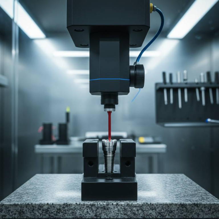
Surface texture in precision subtractive manufacturing governs mechanical performance long after a component leaves the machine envelope. Specifying a surface finish is not merely a cosmetic choice; it directly dictates the tribological coefficient of friction, high-cycle fatigue thresholds, micro-crack initiation rates, and fluid containment capabilities across mission-critical assemblies. Modern multi-axis machining leverages advanced 5-axis machining centers to control tool paths at the sub-micron scale, giving design engineers precise control over isotropic and anisotropic micro-topography.
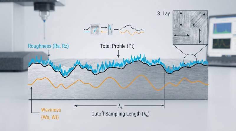
Surface topography consists of three distinct components: roughness (micro-irregularities from tool edge geometries), waviness (macro-errors resulting from machine vibration, deflection, or workpiece chatter), and lay (the predominant directional pattern of the cutter marks). Standardized under ASME B46.1 and ISO 1302, modern metrology utilizes multi-parameter surface characterization to ensure parts survive extreme operational stresses.
Surface Roughness Metrics & Technical Standards: Decoding Ra, Rz, and Drawing Callouts
Specifying roughness requires an understanding of how profilometers sample surface deviations. The most common metric, Roughness Average (Ra), calculates the arithmetical mean deviation of the roughness profile from the central evaluation line across a set cutoff length (typically λc = 0.8 mm for general milling or λc = 0.25 mm for fine micro-milling).
The “Ra Fallacy”: Ra is a two-dimensional mathematical average that completely obscures profile morphology. Two distinct surfaces can possess an identical Ra 0.8 μm value while exhibiting fundamentally different cross-sections: one having wide, rounded plateaus, and the other having sharp, severe peak-to-valley spikes. In dynamic hydraulic sealing or ultra-high vacuum (UHV) interfaces, these sharp spikes rupture elastomeric O-rings or create micro-leak channels, causing immediate pressure degradation despite passing an Ra-only inspection.
To eliminate this failure mode, rigorous engineering drawings combine Ra with Rz (average maximum peak-to-valley height calculated over five consecutive sampling lengths) or Rmax (the absolute maximum peak-to-valley distance). ISO 1302 and ASME Y14.36M provide standard drawing callouts that explicitly dictate material removal requirements, sampling lengths, and required lay orientations (e.g., parallel ‘=’, perpendicular ‘⊥’, crossed ‘X’, or circular ‘C’).
| Roughness Grade (ISO) | Ra (μm) | Ra (μin) | Rz (μm, Approx.) | RMS (μin) | Typical Machining Process |
|---|---|---|---|---|---|
| N10 – N11 | 12.5 – 6.3 | 500 – 250 | 50.0 – 25.0 | 550 – 275 | Heavy roughing, rough turning |
| N8 – N9 | 3.2 | 125 | 12.5 – 16.0 | 140 | Standard CNC milling, high-feed turning |
| N7 | 1.6 | 63 | 6.3 – 8.0 | 70 | Fine milling, standard turning finish |
| N6 | 0.8 | 32 | 3.2 – 4.0 | 35 | High-speed precision milling, diamond turning |
| N5 | 0.4 | 16 | 1.6 – 2.0 | 18 | Micro-milling, fine cylindrical grinding |
| N4 | 0.2 | 8 | 0.8 – 1.0 | 9 | Lapping, superfinishing, polishing |
Direct Machining Finishes: From Standard As-Machined (Ra 3.2 μm) to Optical Micro-Milling (Ra 0.4 μm)
Subtractive tool paths naturally generate a series of periodic cusps (scallops) on the workpiece surface. The theoretical peak-to-valley cusp height (Rth) in single-point turning and face milling is fundamentally governed by the feed per revolution (or feed per tooth) and the cutting tool corner radius.
Rth: Theoretical Cusp Height (mm), f: Feed Rate per Revolution (mm/rev), rε: Tool Corner/Nose Radius (mm)
Achieving varying surface classifications requires targeted spindle kinematic controls:
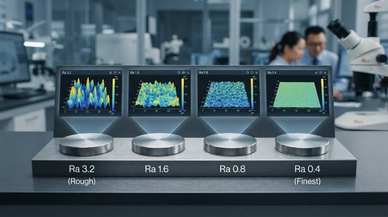
- As-Machined Standard (Ra 3.2 μm / 125 μin): The economic default for non-critical clearance brackets, internal structural ribs, and rough fixtures. Produced using high feed rates (f = 0.25 to 0.35 mm/rev) to minimize spindle cycle time.
- Commercial Smooth (Ra 1.6 μm / 63 μin): Achieved via balanced finishing passes. Ideal for robust face-to-face metal contact, static bolting datums, and non-dynamic flange faces. Supported widely through standard precision CNC milling services.
- Precision Sealing & Bearing Fit (Ra 0.8 μm / 32 μin): Required for standard O-ring sealing channels (MIL-G-5514 / ISO 3601), low-friction sliding ways, and press-fit dowel bores. Demands dynamic tool balancing to G2.5 at 20,000 RPM and fine-pitch wiper insert geometry.
- Optical & Micro-Milling Grade (Ra 0.4 μm / 16 μin): Eliminates manual hand-lapping by employing ultra-rigid 5-axis platforms, PCD/single-crystal diamond tooling, feeds below 0.03 mm/tooth, and sub-micron depth-of-cut passes. This maintains absolute geometric true position (GD&T ≤ 0.005 mm) while yielding a mirror-like finish directly off the machine spindle.
Abrasive Finishing & Bead Blasting: Media Grades, Dimensional Erosion, and Thread Preservation
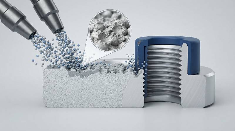
Abrasive blasting is an effective mechanical process for removing directional cutter paths, eliminating burrs, and creating an isotropic satin/matte visual appearance. However, abrasive media impacts also introduce dimensional erosion that must be engineered into the production process.
During standard glass bead blasting, spherical soda-lime glass media is accelerated via compressed air (40 to 80 PSI) against the substrate. Fine media (#120 grit, 70–105 μm bead diameter) produces a fine, low-glare sheen with minimal surface deformation, whereas coarser media (#80 grit, 150–250 μm bead diameter) yields a deeper matte texture that obscures heavy tool marks.
Engineers must account for critical post-machining dimensional realities:
- Dimensional Erosion: Dry bead blasting erodes 0.005 mm to 0.015 mm per side of substrate material depending on blast pressure, dwell time, and angle of impingement.
- Thread & Tolerance Degradation: Unprotected Class 2B/3B internal threads and H7 bearing bores will experience pitch diameter distortion, bell-mouthing, and gauge non-conformance. Critical features produced via high-precision CNC turning require custom masking plugs (silicone or precision-machined PEEK caps) prior to media exposure.
- Alternative Abrasive Methods: Vapor honing (wet slurry blasting) suspends micro-abrasive media in a high-volume water stream, reducing surface erosion to under 0.002 mm while eliminating static media embedment. Mechanical buffing and diamond paste lapping progressively smooth baseline textures down to Ra 0.05 μm for extreme optical or ultra-high vacuum requirements.
Chemical and Functional Post-Processing: Preparing Substrates for Anodizing and Electropolishing
Baseline machining micro-topography heavily influences the final visual appearance, dielectric breakdown, and corrosion resistance of chemical conversion and passivation coatings. Strategic engineering material selection must account for how chemical surface treatments interact with the underlying micro-geometry.
In aluminum alloys (such as Al 6061-T6 and Al 7075-T6), Type II sulfuric anodizing (MIL-A-8625) creates a transparent, porous aluminum oxide layer (5 to 25 μm thick) that highlights any underlying machining variations. If applied directly over an inconsistent Ra 1.6 μm turned surface, tool step-overs and directional tool marks remain visible under direct lighting. Pre-treating the surface with an isotropic #120 bead blast produces a diffuse, non-directional surface that yields a uniform cosmetic finish.
Type III Hardcoat Anodizing (50 μm build-up) creates significant coating growth (50% penetration into substrate, 50% outward growth), which inherently increases baseline surface roughness. An Ra 0.8 μm substrate typically degrades to Ra 1.2–1.6 μm post-hardcoat. Conversely, electropolishing on austenitic 316L stainless steel acts as an anodic dissolution process, removing microscopic peaks faster than valleys. This smooths an Ra 0.8 μm baseline down to Ra 0.4 μm while elevating the surface chromium-to-iron ratio (Cr/Fe ≥ 2.0) for high-purity biopharmaceutical and semiconductor applications.
The Engineering Surface Roughness Decision Matrix: Balancing Tribology, Sealing, and Economics
Surface finish selection requires evaluating four core engineering dimensions: dimensional stability, tribological friction, coating adhesion, and manufacturing cost escalation.
| Surface Finish Type | Target Ra (μm) | Dimensional Retention | Sealing & Dynamic Friction Compliance | Coating / Anodize Compatibility | Relative Cost Factor |
|---|---|---|---|---|---|
| Standard As-Machined | 3.2 | ±0.010 mm | Static clearance only; prone to seal bypass | Cutter paths visible under clear/color anodize | 1.0× (Baseline) |
| Commercial Fine Mill | 1.6 | ±0.008 mm | Static low-pressure gaskets, mechanical mating | Minor tool lines remain visible after etching | 1.2× |
| Precision Micro-Mill | 0.8 | ±0.005 mm | Dynamic hydraulic seals, vacuum elastomer O-rings | Excellent base for high-spec hard anodizing | 1.6× |
| Optical Diamond Mill | 0.4 | ±0.0025 mm | UHV metal-to-metal knife-edge seals, optical reflectors | Requires specialized non-etch clean lines | 2.5× – 3.2× |
| Glass Bead Blast (#120) | 1.6 – 3.2 | -0.010 mm per face | Unsuitable for dynamic seals (abrasive peaks) | Optimal matte visual sheen for Type II/III anodizing | 1.3× (incl. manual handling) |
| Electropolished 316L | 0.2 – 0.4 | -0.005 mm per face | Extreme purity; prevents bio-film and particulate adhesion | Passivated surface; excellent corrosion barrier | 2.0× – 2.8× |
Proprietary Methodology: The Tyneen Selective Surface Tolerancing Matrix (SSTM™)
Demanding full-body Ra 0.4 μm finishes or unmasked global bead blasting across complex geometric components leads to unnecessary scrap and inflated cycle times. Tyneen solves this through the proprietary Selective Surface Tolerancing Matrix (SSTM™) workflow.
The SSTM™ protocol executes a three-tier geometric segmentation directly within the CAD/CAM environment:
- Zone A (Functional Primary Datums & Dynamic Sealing Channels): Programmed for direct 5-axis micro-milling (Ra 0.4–0.8 μm). Tool paths use continuous trochoidal lead-ins to avoid tool dwell marks. No manual abrasives are permitted in Zone A.
- Zone B (Threaded Fasteners, Dowel Bores, and Critical Alignment Steps): CNC turned/milled to nominal tolerances (Ra 1.6 μm). In downstream operations, Zone B features are isolated using reusable high-temperature silicone plugs or custom-machined PEEK masking blocks.
- Zone C (Cosmetic Housings, External Non-Mating Shells, and Recessed Pockets): Subjected to automated #120 glass bead blasting at 50 PSI. Zone C absorbs all visual tool mark transitions without impacting the dimensional integrity of Zone A or Zone B.
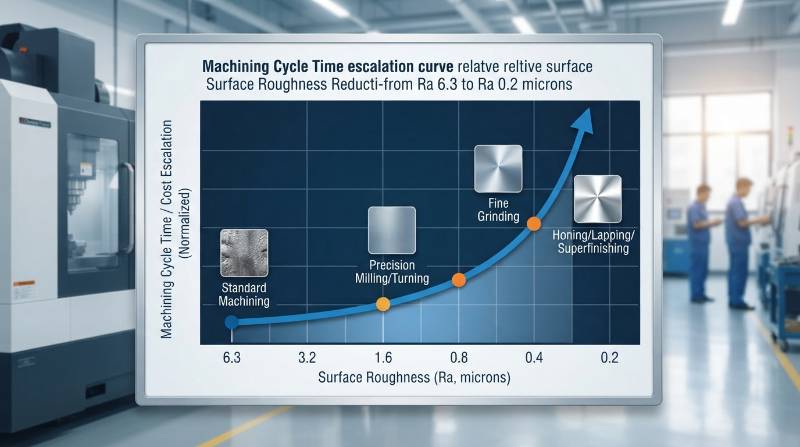
By segregating these surfaces during the DFM phase, SSTM™ reduces total cycle times by up to 40% compared to global ultra-fine machining, while protecting critical tolerances.
Extreme Niche Case: Ra 0.4 μm Micro-Milled Vacuum Channels with Selective #120 Bead Blasting
A recent semiconductor robotic end-effector manifold presents a classic surface finish challenge: the part required helium leak-tight (≤ 1.0 × 10⁻⁹ mbar·L/s) Ra 0.4 μm micro-milled sealing channels, alongside a uniform, non-glare #120 fine bead-blasted external exterior—all with zero abrasive particulate contamination in the internal fluid circuits.
Manufacturing Execution Summary:
- Workpiece Substrate: Aerospace-grade Aluminum 6061-T651 billet.
- 5-Axis Machining Platform: DMG MORI NMV 5000 DCG with a 30,000 RPM high-frequency synchronized spindle.
- Channel Cutting Strategy: PCD (Polycrystalline Diamond) ball-end cutters running at Vc = 450 m/min, feed per tooth fz = 0.018 mm, and an axial step-over of 0.025 mm to achieve a pristine Ra 0.32 μm and Rz 1.4 μm finish directly off the machine.
- Custom Masking Isolation: Tyneen additive tooling engineers fabricated custom-molded silicone gaskets clamped beneath CNC-machined aluminum fixtures to completely seal the micro-grooves and internal ports during blasting.
- Abrasive Media Exposure: Uniform #120 spherical glass bead blasting applied at 45 PSI across external surfaces, achieving an isotropic satin finish (Ra 2.4 μm) with zero media penetration into the seal track.
- Multi-Stage Ultrasonic Decontamination: Four-stage ultrasonic wash in an ISO Class 6 cleanroom environment using deionized water at 65°C and analytical surfactant chemistry, followed by residual particle verification via scanning electron microscopy (SEM).
Tyneen Precision Metrology & Multi-Axis Manufacturing Verification Standards
Precision surface callouts require high-grade metrology verification. Tyneen maintains a certified quality infrastructure registered under ISO 9001:2015, IATF 16949, and AS9100D standards, operating in a temperature-controlled metrology laboratory (20°C ± 0.5°C).
Our quality verification protocol deploys industry-standard inspection hardware for every production run:
- Contact Stylus Profilometry: Mitutoyo Surftest SJ-410 systems utilizing diamond-tipped styli (2 μm tip radius) to capture Ra, Rz, Rmax, and Abbott-Firestone bearing curve parameters per ISO 4287.
- Coordinate Metrology: Zeiss PRISMO 3D CMMs delivering sub-micron spatial verification with maximum permissible error MPEe = 0.9 + L/350 μm, ensuring that pre- and post-surface processing remain fully compliant with GD&T profile tolerances down to ±0.005 mm.
- Non-Contact Optical Interferometry: High-resolution white-light interferometers deployed for micro-milled and diamond-turned optical faces, generating 3D surface color topologies without touching sensitive part datums.
- Digital Inspection Certificates: Full metrology documentation—including profilometer roughness charts, Zeiss CMM inspection reports, and material mill test reports (MTR)—accompanies every delivered production batch.
Technical Comparisons & Empirical Verification: Resolving Machining vs. Finishing Conflicts
1. As-Machined Ra 1.6 μm vs. Bead Blasting (#120) for Anodizing Uniformity
Machining aluminum to Ra 1.6 μm generates directional micro-grooves that reflect incident light unevenly. When clear or color anodizing is applied without abrasive pre-treatment, standard alkaline etching often fails to hide tool transition steps, causing noticeable visual banding.
Applying a controlled #120 glass bead blast fractures these micro-groove peaks into a non-directional, semi-spherical dimpled profile (Ra 2.0–2.8 μm). This diffuse profile scatters ambient light uniformly, ensuring an even, non-reflective matte finish across complex anodized components.
2. Direct Ra 0.4 μm Micro-Milling vs. Manual Abrasive Lapping
Manual lapping uses loose abrasive slurries on cast iron plates to achieve Ra 0.2–0.4 μm. However, hand lapping relies on operator technique and often introduces edge roll-off, compromising perpendicularity and bore cylindrical true position.
In contrast, 5-axis high-speed micro-milling on DMG MORI machining centers uses rigid diamond tooling and tight CAM step-overs to produce Ra 0.4 μm finishes directly. This approach maintains strict true-position tolerances (≤ 0.005 mm) and crisp, unrounded edges across complex intersecting surfaces.
3-Step Production Pathway: Fast-Track Your High-Precision Surface Finished Components
Launch Your Precision Finished Component Production
Leverage Tyneen’s multi-axis CNC machining, selective surface masking, and metrology inspection to streamline your production timeline.
Step 1: Upload 3D CAD/STEP Models & 2D Technical Prints
Submit your 3D CAD files (.STEP, .IGES, .X_T) along with 2D engineering drawings specifying critical surface roughness callouts (Ra, Rz), datum faces, and masking boundaries.
Step 2: Automated DFM Surface Analysis & Quote within 2 Hours
Our metrology and machining specialists evaluate your geometry for tool reach, cusp height optimization, and masking requirements, providing an actionable DFM analysis and quote in under 2 hours.
Step 3: Precision Manufacturing, Zeiss CMM Metrology, and Global Dispatch
Components are machined on DMG MORI 5-axis centers, processed through verified finishing lines, inspected via Zeiss CMM and Mitutoyo profilometers, and shipped with complete inspection certificates in as few as 3 to 7 business days.
Frequently Asked Questions: CNC Surface Roughness and Mechanical Finishing
What is the mathematical conversion ratio between Ra and RMS?
Root Mean Square (RMS or Rq) averages surface peak deviations by squaring each measurement, making it more sensitive to occasional high peaks and deep valleys than Ra. For standard subtractive CNC milling and turning tool paths, the approximate conversion is RMS ≈ Ra × 1.11 (or Ra ≈ RMS × 0.90). However, precise engineering prints should always specify one explicit parameter to eliminate ambiguity during metrology inspection.
How much dimensional stock loss should be accounted for during glass bead blasting?
Standard glass bead blasting (#100 to #120 grit at 50–60 PSI) removes approximately 0.005 mm to 0.015 mm (0.0002 in to 0.0006 in) of substrate per side. For critical fit dimensions (such as H7 bearing bores or Class 2B/3B threads), parts should either be machined slightly oversize or protected using custom masking plugs to prevent dimensional non-conformance.
What is the recommended surface finish for dynamic vs. static O-ring seals?
For static face seals (non-moving vacuum or hydraulic flanges), an Ra 0.8 μm to 1.6 μm (32 to 63 μin) finish is recommended. For dynamic reciprocating or rotary seals, surfaces should target Ra 0.2 μm to 0.4 μm (8 to 16 μin) with a maximum Rz ≤ 1.6 μm to prevent elastomeric abrasion, premature seal wear, and micro-channel leak paths.
How does Type II and Type III hardcoat anodizing affect baseline surface roughness?
Type II anodizing (coating thickness 10–15 μm) typically preserves the underlying surface roughness, increasing Ra by roughly 0.1 to 0.2 μm due to chemical desmutting and acid etch pre-treatment. In contrast, Type III Hardcoat Anodizing (50 μm thick) creates a rougher micro-crystalline oxide growth, often raising an initial Ra 0.8 μm surface to Ra 1.2 μm to 1.6 μm post-coating.