Aluminum vs. Steel Thermal Expansion Calculator for CNC
CNC Thermal Expansion Calculator: Aluminum vs. Steel
Precision in CNC machining is a moving target. As spindle speeds increase and cycle times compress, thermal drift becomes the primary cause of dimensional non-conformance.
The Coefficient of Thermal Expansion (CTE) measures how much a material’s length changes per degree of temperature fluctuation. For high-precision shops, failing to account for this leads to scrapped parts and failed assemblies.
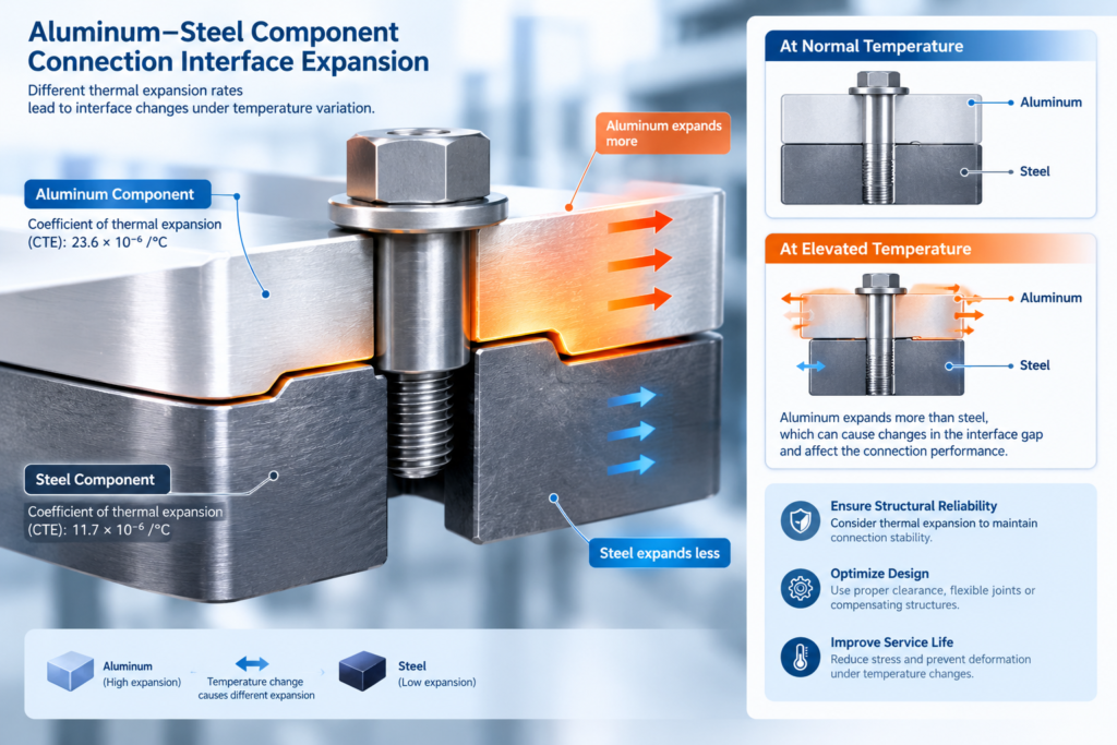
Aluminum expands at approximately 23.1 µm/m°C, while Carbon Steel expands at roughly 11.0 to 12.5 µm/m°C. This means an aluminum part will grow nearly twice as much as a steel part when exposed to the same internal spindle heat or ambient shop temperature shifts.
Interactive Thermal Drift & CTE Calculator
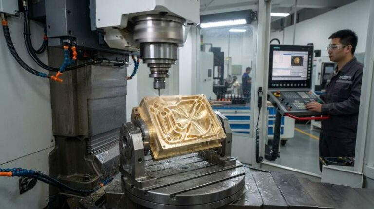
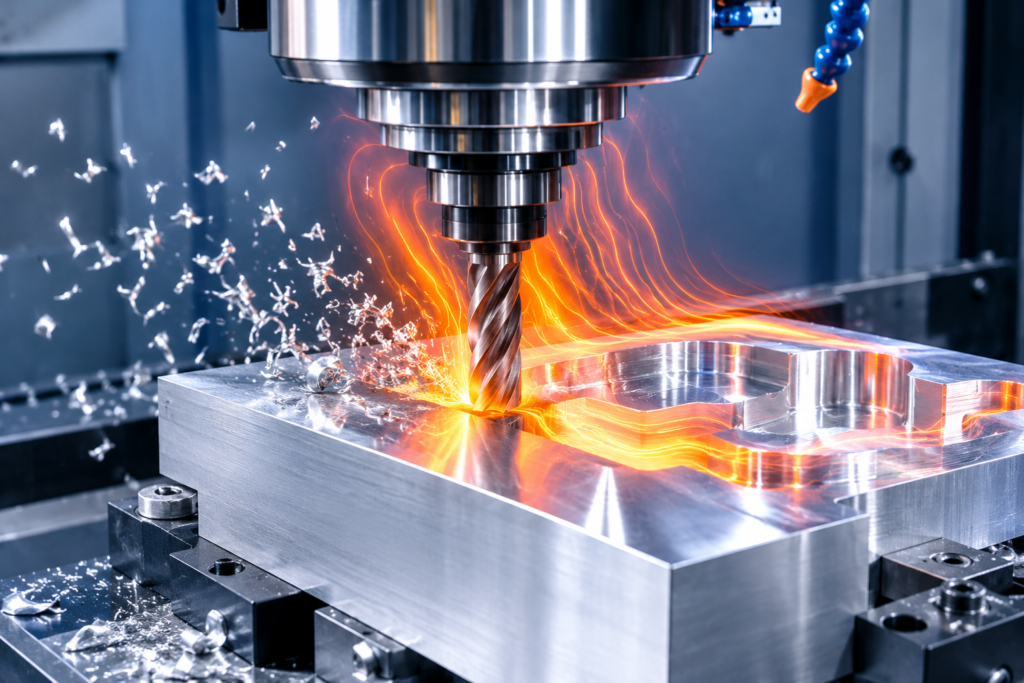
Modern 2026 machining environments utilize high-pressure coolant and 20,000+ RPM spindles. These factors create localized heat zones that standard formulas often ignore.
Use the logic below to estimate your part growth. For mission-critical tolerances, our Precision Machining Services utilize real-time thermal compensation sensors to mitigate these variables.
| Material Alloy | CTE (10⁻⁶/°C) | Growth per 100mm per 10°C |
|---|---|---|
| 6061 Aluminum | 23.6 | 0.0236 mm |
| 7075 Aluminum | 23.2 | 0.0232 mm |
| 304 Stainless Steel | 17.3 | 0.0173 mm |
| 1018 Carbon Steel | 11.7 | 0.0117 mm |
| D2 Tool Steel | 10.4 | 0.0104 mm |
The standard formula for linear expansion is: ∆L = L₀ × α × ∆T. (Change in length = Original length × CTE × Change in temperature).
The Tyneen Thermal Drift Protocol (TDP) for Bimetallic Assemblies
When aluminum and steel components interface, differential thermal growth causes mechanical stress or seizure. We developed the Tyneen Thermal Drift Protocol (TDP) to solve this.
This proprietary 3-step framework ensures bimetallic assemblies maintain integrity across a 100°C operating range:
- Phase 1: Thermal Baseline Calibration: Establish the “Golden Temperature” (usually 20°C/68°F) for all metrology. Every micron of deviation is logged relative to this baseline.
- Phase 2: Differential Expansion Mapping: We calculate the “Gap Variance” between the aluminum housing and the steel shaft. This dictates the required CNC Tolerance Standards for the interference fit.
- Phase 3: Active Spindle Compensation: Use machine control offsets to adjust tool paths in real-time as the spindle warms up, neutralizing the “first-part-of-the-day” error.
Aluminum vs. Steel: Material Science and Heat Dissipation
Aluminum’s high thermal conductivity (approx. 130-230 W/m·K) allows it to dissipate heat faster than steel (approx. 15-50 W/m·K). While this benefits tool life, it also means the entire part reaches a uniform, expanded state much quicker.
In cryogenic machining environments—a growing trend in 2026 for medical implants—the CTE of 7075 aluminum becomes non-linear. Steel remains more dimensionally stable at extreme lows, but its machinability rating drops as it becomes brittle.
Choosing the right alloy requires balancing these thermal properties. Refer to our Material Selection Guide for a full breakdown of machinability versus thermal stability.
“Thermal conductivity is the engine of heat transfer, but CTE is the map that tells the part where to move.” — Tyneen Engineering Lab Data, 2026
Beyond the Lab: Real-World Factors in Thermal Drift
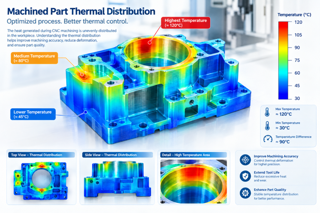
Theoretical CTE values assume a uniform temperature increase. On a 2026 shop floor, this is rarely the case. We have found that coolant pressure and ambient shop temperature often matter more than the data sheet values.
High-pressure coolant (1000+ PSI) can actually over-cool the exterior of a part while the core remains hot from heavy milling. This creates internal thermal stress.
Furthermore, spindle heat soak—where the heat from the motor migrates through the casting to the tool holder—can cause a Z-axis shift of up to 30 microns over a four-hour shift. Relying solely on a basic metal thermal drift calculation without accounting for machine “warm-up” is a recipe for failure.
Integrating CTE Data into CAD/CAM Workflows
Modern CAD/CAM software now allows for “Digital Twin Thermal Modeling.” By inputting the expected ambient temperature of the assembly’s end-use environment, engineers can design “pre-distorted” geometries.
For example, if an aluminum part must fit a steel bearing at 80°C, the CNC program should cut the aluminum bore slightly undersized at the 20°C shop temperature.
Advanced CAM strategies now include “Thermal Offset Probing.” The machine stops mid-cycle, probes a known artifact, calculates the drift, and updates the work coordinate system (WCS) automatically. This is essential for long-cycle aerospace components made from 6061 aluminum.
Frequently Asked Questions
How do I calculate thermal expansion in CNC?
Multiply the original dimension by the material’s CTE and the temperature difference (∆T). Ensure your ∆T is the difference between the shop’s ambient temperature and the standard 20°C (68°F) metrology baseline.
Why does aluminum expand more than steel?
Aluminum has a less rigid atomic structure and weaker metallic bonds compared to steel. This allows atoms to vibrate and move further apart as kinetic energy (heat) increases, resulting in a higher CTE.
How does coolant affect part size?
Coolant acts as a thermal stabilizer. However, inconsistent coolant flow can cause “thermal shock” or localized expansion, leading to warping. Maintaining a chilled coolant system at a constant temperature is vital for sub-ten-thousandth tolerances.
Expert Review and Technical References
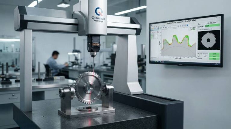
This guide was reviewed by the Tyneen Engineering Team to ensure metrology accuracy. Our data is derived from real-world testing on 5-axis machining centers and high-precision coordinate measuring machines (CMM).
Expert Bio: Robert Chen, Senior Mechanical Engineer at Tyneen, specializes in thermal dynamics and precision manufacturing. With over 15 years in aerospace machining, Robert led the development of the TDP framework for bimetallic aircraft components.
Technical Bibliography
- ASTM E228 – Standard Test Method for Linear Thermal Expansion of Solid Materials. ASTM International
- NIST Engineering Statistics Handbook: Thermal Properties of Metals. National Institute of Standards and Technology
- Journal of Materials Processing Technology: Thermal Drift in High-Speed Spindles (2025 Edition).