5-Axis DFM: How to Minimize Tool Changes and Costs
Designing for 5-Axis Milling: Architectural Strategies to Minimize Tool Changes
In multi-axis manufacturing, machine runtime is frequently dominated not by chip removal, but by non-cutting kinematic overhead. Transitioning from traditional 3-axis multi-setup operations to continuous simultaneous 5-axis machining consolidates operations into a single coordinate datum. However, unoptimized part geometry often triggers an excessive number of cutter swaps in CAM routines.
When selecting precision 5-axis CNC milling services, engineers must recognize that every automatic tool changer (ATC) actuation introduces 8 to 15 seconds of chip-to-chip latency. Across small-to-medium batch runs, excessive tool calls cause thermal drift across spindle bearings, compromise positional repeatability, and compound non-recurring engineering (NRE) setup expenses.
Minimizing tool changes demands strict geometric harmonization at the CAD phase. By aligning internal corner radii, managing depth-to-diameter aspect ratios, and planning continuous 5-axis toolpaths, design teams can consolidate entire operations down to a compact, single-carousel tool envelope.
The 5-Axis Tool Consolidation Framework: Geometric Evaluation & Decision Matrix
Engineering multi-axis components without a standardized tooling matrix forces CAM programmers to load niche, micro-diameter cutters for minor design features. This practice fragments cutting strategies and drives up cycle times. Tyneen applies a four-pillar design for manufacturability (DFM) evaluation framework to eliminate redundant tooling directly within the model structure:
- Feature Geometry Uniformity: Harmonizing pocket base fillets, floor radii, and corner chamfers to match a shared standard cutter diameter.
- Tool Aspect Ratio Limits (L/D): Enforcing cavity depth thresholds below 4:1 to avoid cantilever deflection and allow unified roughing-finishing passes.
- Continuous Swarf & Flank Accessibility: Designing wall drafts that leverage simultaneous B- and C-axis rotational tilting for flank milling instead of multi-pass point contouring.
- Total Machining Efficiency Index: Evaluating the ratio of active material removal rate (MRR) against total spindle non-cutting cycles, targeting a minimum 85% in-cut spindle utilization.
| Feature Category | Unoptimized CAD Geometry | Consolidated DFM Geometry | Tooling Reduction Impact |
|---|---|---|---|
| Internal Vertical Radii | Mixed R1.0 mm, R2.0 mm, R3.0 mm corners | Standardized R3.5 mm for ⌀6 mm end mill | Replaces 3 micro-tools with 1 rigid cutter |
| Cavity Depth-to-Width | L/D > 6:1 (Deep narrow pockets) | L/D ≤ 3.5:1 with drafted side walls (≥ 2°) | Eliminates stepped-reach extension toolholders |
| 3D Freeform Surfaces | Tight transitional fillets requiring ball mills | Swept planar surfaces fitted for barrel cutters | Merges semi-finish and finish passes into 1 tool |
| Undercut Features | Step-down pockets requiring spherical lollipop tools | Line-of-sight angular draft accessible via table tilt | Eliminates dedicated undercutting cutters |
Geometric Feature Standardization in 5-Axis DFM
Standardizing geometric details across your CAD solid model directly reduces the cutting tool inventory required to machine the part. Even minor corner radius variations force the CAM software to call separate cutters, multiplying cycle times.
Standardizing Internal Fillet Radii and Cutter Diameter Proportions
A frequent error in multi-axis CAD design is setting an internal vertical corner radius identical to a nominal cutter radius (for example, modeling an R3.0 mm fillet and machining it with a ⌀6 mm end mill). When a tool enters an identical corner, its radial engagement angle spikes from roughly 45° to 180° instantly.
This surge in cutting forces induces dynamic chatter, compromises surface finish, and triggers premature tool chipping. CAM programmers typically compensate by swapping to a smaller micro-diameter end mill (e.g., ⌀3 mm or ⌀4 mm) to clear the residual material. This adds a dedicated tool change cycle and forces lower feed rates.
“Internal corner radii must always be modeled at least 10% to 15% larger than the radius of the standard milling cutter (Radius_internal ≥ 1.15 × Radius_tool). Sizing corner fillets at R3.5 mm allows a rigid ⌀6 mm tool to sweep through corners smoothly along a continuous circular arc without slowing down.”
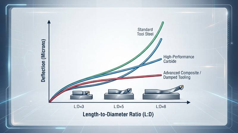
Cutter Deflection Dynamics and Limiting Cavity Aspect Ratios (L/D ≤ 4:1)
As pocket depths increase relative to tool diameter, tool rigidity drops exponentially. A cutting tool functions as a cantilevered cylindrical beam. Its physical deflection under cutting loads follows standard structural mechanics:
Where δ = Tool Tip Deflection (mm), F = Radial Cutting Force (N), L = Tool Overhang Length (mm), E = Tool Substrate Modulus of Elasticity (Tungsten Carbide ≈ 600 GPa), I = Area Moment of Inertia (π × D⁴ / 64)
Because deflection scales with the third power of length (L³) and inversely with the fourth power of diameter (D⁴), doubling the tool overhang length increases deflection eightfold. When machining tough engineering alloys and aerospace materials like Ti-6Al-4V or 17-4 PH stainless steel, deflection-induced chatter forces programmers to introduce dedicated stubby roughers, extended semi-finishers, and slow finish tools.
Restricting deep cavities to length-to-diameter aspect ratios of L/D ≤ 4:1 maintains tool stiffness. This allows a single, high-rigidity bull-nose end mill to execute heavy dynamic roughing, step-down pocket clearing, and finish wall contours without tool changes.
Eliminating Micro-Undercuts and Maximizing Continuous Swarf Milling
Small undercuts, reverse draft angles, and recessed O-ring grooves often require specialized spherical lollipop cutters, T-slot cutters, or slitting saws. Each dedicated cutter profile demands its own magazine slot, probing routine, and feed calibration.
True 5-axis machining allows parts to rotate along simultaneous B and C rotary axes. This presents complex geometry directly to standard tools without requiring dedicated undercut hardware. By maintaining clear line-of-sight access in the CAD model, designers enable continuous swarf (flank) milling.
Swarf milling cuts across the full cylindrical side of an end mill rather than its tip. This technique finishes contoured aerodynamic draft walls and structural ribs in a single continuous pass, eliminating multiple fine-step ball-nose passes and their associated cutter changes.
Advanced Tooling Strategies: Circle Segment Cutters and Path Consolidation
Shifting from traditional ball-nose finishing to modern tool geometries significantly reduces multi-axis cycle times while maintaining superior surface consistency.
Deploying Barrel and Lens Cutters for High-Feed 5-Axis Surface Finishing
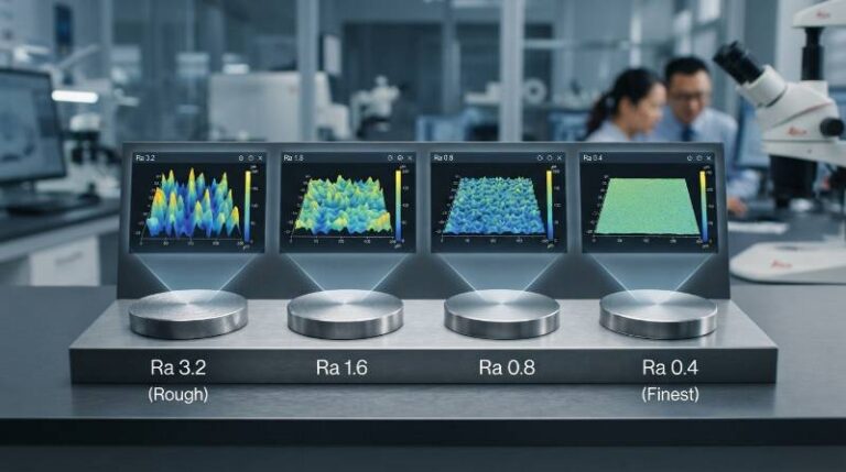
When finishing curved 3D surfaces with standard ball-nose cutters, achieving low surface roughness (such as Ra 0.4 μm to Ra 0.8 μm) demands tiny step-over increments (typically 0.1 mm to 0.3 mm). This requirement forces programmers to split cycles into semi-finishing and fine-finishing operations using different tools. Circle segment end mills (barrel, lens, and taper-form geometries) overcome this limitation through expanded contact mechanics.
A circle segment cutter pairs a standard shank diameter (e.g., ⌀12 mm) with an effective lateral cutting profile radius ranging from R250 mm to over R1000 mm. This large profile dramatically reduces the scallop (cusp) height left behind on curved walls.
Where h = Scallop Cusp Height (μm), ae = Step-over Distance (mm), Reff = Effective Cutting Edge Profile Radius (mm)
Because the effective profile radius (Reff) is substantially larger than a standard ball-nose radius, step-over values can be widened by 300% to 500% while keeping scallop heights under 0.2 μm. Leveraging our advanced precision machining capabilities, Tyneen applies these circle segment paths to complete rough-to-finish transitions using a single profile cutter, cutting out the intermediate finishing passes entirely.
Consolidating Roughing and Finishing with Optimized Bull-Nose Tools
High-feed bull-nose (toroidal) end mills combine flat end-face cutting dynamics with reinforced corner corner-radii (e.g., ⌀12 mm with R1.5 mm corner). This geometry directs cutting forces axially along the spindle centerline rather than radially, substantially reducing deflection.
By adjusting cutting speed (Vc) and radial depth of cut (ae), CAM programmers can use a single bull-nose cutter to clear bulk stock via trochoidal milling, and then finish external profiles in the same tool setup:
- Trochoidal Roughing Phase: High axial depth (ap = 1.5 × D), low radial engagement (ae = 0.1 × D), and elevated feed per tooth (fz = 0.15 mm/z) clear raw stock quickly.
- Adaptive Semi-Finish/Finish Phase: Reduced axial feed and light radial cleanup (ae = 0.02 × D) eliminate surface deflection and clean part profiles within dimensional tolerances.
Eliminating dedicated roughing-to-finishing cutter swaps removes tool seating inaccuracies, preserves spindle thermal stability, and cuts total machining overhead.
The Economics of 5-Axis ATC Overhead: Cycle Time vs. Tool Library Footprints
The financial impact of unoptimized tool changes accumulates rapidly across production schedules. Design choices directly influence how many tool calls a given part requires.
Quantitative Financial and Cycle Time Analysis of ATC Latency
A tool change on a high-precision 5-axis simultaneous machining center involves a multi-step sequence that goes well beyond the mechanical arm swap:
- Spindle deceleration from operational velocity (e.g., 18,000 RPM to 0 RPM) and axis retraction to tool-change home coordinates (2.5 to 4.0 s).
- Magazine indexing, mechanical arm extraction, tool carousel swap, and spindle drawbar clamping (3.5 to 6.0 s).
- Spindle acceleration back to target cutting speed, non-contact laser tool length/wear verification, and rapid axis approach to the part surface (3.0 to 5.0 s).
Every tool change adds roughly 9 to 15 seconds of non-productive dwell time. Machining a complex component that requires 18 separate tools across roughing, semi-finishing, corner clearing, and detailing burns over 4.5 minutes purely in tool handling latency per component.
| Batch Size | Unoptimized (18 Tool Swaps) | DFM Consolidated (7 Tool Swaps) | Time Saved | Net Cost Reduction |
|---|---|---|---|---|
| 50 units | 3.75 hours dwell | 1.45 hours dwell | 2.30 hours | $322.00 |
| 250 units | 18.75 hours dwell | 7.29 hours dwell | 11.46 hours | $1,604.40 |
| 1,000 units | 75.00 hours dwell | 29.16 hours dwell | 45.84 hours | $6,417.60 |
| 5,000 units | 375.00 hours dwell | 145.80 hours dwell | 229.20 hours | $32,088.00 |
Optimizing for Standard 8-to-12 Tool Carousel Envelopes to Lower NRE Costs
Standard 5-axis machines feature compact tool changers typically holding 24 to 32 tools. In high-mix precision job shops, setting aside dedicated magazine bays for standardized tooling (facemill, dynamic rougher, standard chamfer, metric taps, and Renishaw probe) leaves roughly 8 to 12 empty slots available for part-specific cutters.
Designing geometry that fits within an 8-to-12 tool envelope avoids manual tool staging, custom offline presetting, and intermediate magazine swaps. By eliminating these setup demands, machine shops can run parts immediately, which substantially reduces initial NRE and CAM programming costs.
Thin-Walled Aerospace Ti-6Al-4V Impellers: Benchmark Case for Single-Setup Tool Minimization
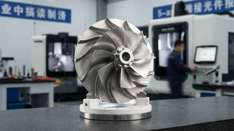
Machining thin-walled titanium components presents a classic engineering tradeoff: balancing cutter engagement against severe vibration risks. Tyneen recently engineered a simultaneous 5-axis production process for an aerospace closed impeller in Titanium Grade 5 (Ti-6Al-4V), an alloy compliant with ASTM B348 specifications.
Initial Part Design Bottlenecks:
- Internal blade transition root fillets varied arbitrarily between R1.5 mm, R2.2 mm, and R3.5 mm.
- Deep blade inter-spacing required long-reach ball-nose cutters with excessive aspect ratios (L/D > 5.5:1), inducing chatter.
- The CAM program relied on 14 dedicated tools, producing a cycle time of 118 minutes per impeller along with visible cutter blend mismatch marks.
Tyneen DFM Optimization Strategy:
- Harmonized all internal root fillet transitions to a uniform R2.5 mm, allowing clearance for a single ⌀4 mm reinforced bull-nose end mill.
- Replaced point-contact ball-nose finishing on the thin-walled (1.2 mm profile) blade flanks with a 5-axis circle segment conical barrel tool (Reff = 450 mm).
- Merged intermediate clearing and wall semi-finishing into a unified dynamic 5-axis trochoidal path using high-pressure through-spindle coolant (70 bar).
Validated Production Results:
- Total dedicated tools cut by 50%, dropping from 14 down to 7 tools.
- Overall cycle time dropped by 42%, falling from 118 minutes down to 68.4 minutes per part.
- Blade profile surface finish achieved Ra 0.32 μm (beating the Ra 0.4 μm requirement) with zero blend lines.
- Zeiss CMM coordinate metrology verified true position within ±0.005 mm across all blade datum points without intermediate cutter offsets.
Industrial Verification & Metrology Infrastructure: Tyneen Precision Machining Systems
Consolidating tooling paths requires exceptional machine dynamic stability and strict thermal control. Tyneen operates a precision multi-axis manufacturing facility certified to ISO 9001:2015, IATF 16949 (Automotive), and AS9100D (Aerospace) quality standards.
Our machining floor utilizes high-end simultaneous 5-axis machining centers, including DMG MORI duoBLOCK and Hermle high-speed milling systems. These machines feature linear direct-drive scales, active thermal expansion compensation, and high-pressure through-spindle cooling channels rated up to 1000 PSI (70 bar).
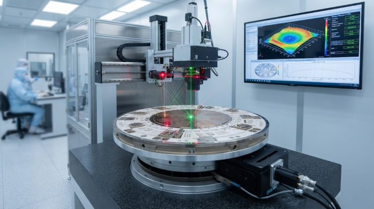
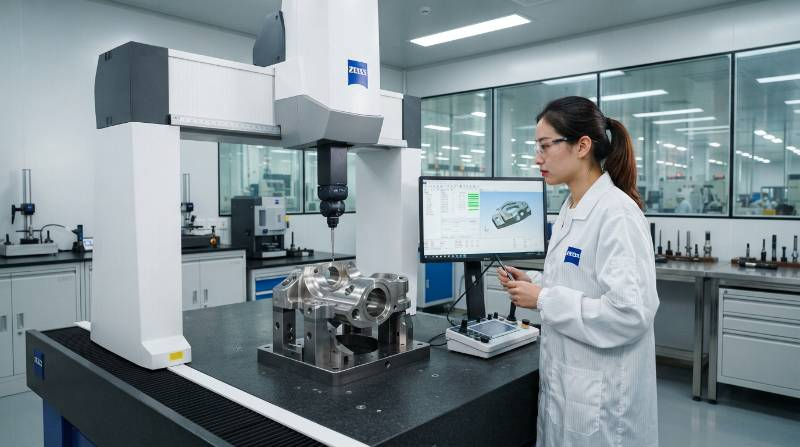
Part validation is handled via automated Renishaw on-machine kinematic probes alongside high-precision coordinate measuring machines. Operating in a strictly climate-controlled metrology laboratory (held at 20°C ±0.5°C), our Zeiss PRISMO CMM platforms provide sub-micron volumetric accuracy (0.5 + L/500 μm), providing certified First Article Inspection (FAI) reports and continuous Statistical Process Control (SPC) for high-reliability production runs.
Substantiating Quality vs Efficiency: Quantitative Technical Tradeoffs and Inspection
Consolidating toolpaths directly influences part geometric tolerances, datum consistency, and surface finish. Comparing these production strategies highlights the key technical tradeoffs involved.
Comparative Analysis: Multi-Setup 3-Axis vs Tool-Optimized 5-Axis Machining
Producing complex parts across multiple 3-axis setups introduces fixture alignment errors, requires larger cutting inventories, and extends cycle times relative to integrated 5-axis milling.
| Machining Parameter | Multi-Setup 3-Axis Milling | 3+2 Axis Positional Milling | Tool-Optimized Simultaneous 5-Axis |
|---|---|---|---|
| Setup/Fixture Count | 3 to 5 separate vise/soft-jaw setups | 1 or 2 modular clamping fixtures | 1 single setup (Dovetail / Zero-point) |
| Tool Library Size | 15 to 25 tools (long reach required) | 12 to 18 tools (stepped tools) | 6 to 10 standardized short-reach tools |
| Positional Accuracy | ±0.025 mm (Datum shift stacking) | ±0.012 mm (Indexing accuracy) | ±0.005 mm (True single-datum baseline) |
| Surface Finish Capability | Ra 1.6 μm to Ra 3.2 μm (step marks) | Ra 0.8 μm to Ra 1.6 μm | Ra 0.4 μm (continuous barrel milling) |
| Relative Production Cost | High (Extensive labor, fixturing) | Medium (Balanced cycle time) | Lowest overall (Minimizes spindle dwell) |
Verifying Critical Tolerances and Wall Thickness Without Secondary Cutter Resets
Running combined roughing and finishing paths on a single cutter introduces tool-wear variables that must be tracked to maintain thin-wall stability. Tyneen integrates a closed-loop metrology workflow on the production floor:
- Non-Contact Laser Presetting: Spindle-integrated Blum laser systems verify tool runout (TIR < 0.002 mm), cutter tip radius wear, and tool length dynamically at operational cutting RPM.
- In-Process Probing Iterations: Renishaw OMP60 optical transmission probes inspect web wall deflection and critical datum faces directly on the machine table between dynamic roughing and final wall sweeping.
- CMM Point Cloud Comparison: Final Zeiss coordinate metrology records GD&T true position, profile-of-a-surface, and wall parallelism down to sub-micron accuracy, fully confirming drawing tolerances before shipping.
The 3-Step Rapid 5-Axis DFM Optimization Pathway
To eliminate tool change bottlenecks and minimize production costs, Tyneen provides a streamlined design-to-production workflow for engineering and sourcing teams:
Tyneen Rapid Precision Engineering Onboarding
- Step 1: Digital CAD Model Submission
Export your part model as a STEP, IGES, or native Parasolid file, alongside a 2D PDF print defining critical GD&T geometric tolerances. - Step 2: Automated DFM & Tooling Footprint Analysis
Within 2 hours, Tyneen engineers analyze your model geometry, identifying radius mismatches, draft issues, and opportunities to consolidate cutters into an 8-to-12 tool envelope, delivered with a transparent quote. - Step 3: Precision Machining & Validated Global Dispatch
Following CAM approval, your components run on high-speed 5-axis DMG MORI or Hermle platforms, undergo Zeiss CMM FAI metrology verification, and ship globally via expedited freight.
Frequently Asked Questions (FAQ): 5-Axis Tool Optimization & DFM
Does reducing tool changes in 5-axis milling compromise part surface roughness (Ra)?
No. In fact, consolidating toolpaths frequently improves surface consistency. Repeated tool changes often introduce minor micro-step witness marks where the cutting paths overlap, caused by tool runout or slight thermal shifts in the spindle.
By moving to modern circle segment (barrel) cutters and continuous 5-axis swarf milling paths, parts achieve uniform finishes of Ra 0.4 μm or better. A single cutter finishes the entire surface blend, eliminating witness lines entirely.
How does spindle collision clearance affect minimum tool length in 5-axis milling?
The spindle clearance envelope defines the shortest cutting tool you can run without risking collisions between the spindle head, tool holder, and workpiece. Using standard steep-taper chucks often forces programmers to switch to long, chatter-prone cutters to clear part features.
To avoid using excessively long tools, engineers should maintain open clearance angles of at least 15° to 30° around deep cavity features. At the machine, slim-profile HSK-shrink-fit or hydraulic tool holders allow short, rigid cutters to access tight spaces without spindle collisions.
What is the recommended ratio between cavity depth and minimum corner radius?
As a best-practice guideline, keep cavity depths within 3× to 4× the nominal tool diameter (L/D ≤ 4:1). Internal vertical corner radii should be designed at least 15% larger than the cutter radius (R_internal ≥ 1.15 × R_tool).
For example, in a 24 mm deep cavity, design the internal vertical corner radii to at least R3.5 mm. This geometry allows a rigid ⌀6 mm end mill to clear the pocket and corners in a single setup, avoiding the need for a secondary micro-diameter cutter change.
How does Tyneen manage tool wear during consolidated roughing and finishing paths?
Tyneen uses automated non-contact Blum laser tool measurement systems inside the machine enclosure. Between roughing and finish profiling operations, the system checks cutter length and radial edge condition at full operating RPM.
If measured flank wear approaches pre-set process thresholds (typically 0.015 mm in aerospace alloys), the CNC controller automatically applies tool offset compensation macros or indexes to a redundant twin cutter stored in the magazine, ensuring critical dimensions remain well within tolerance.