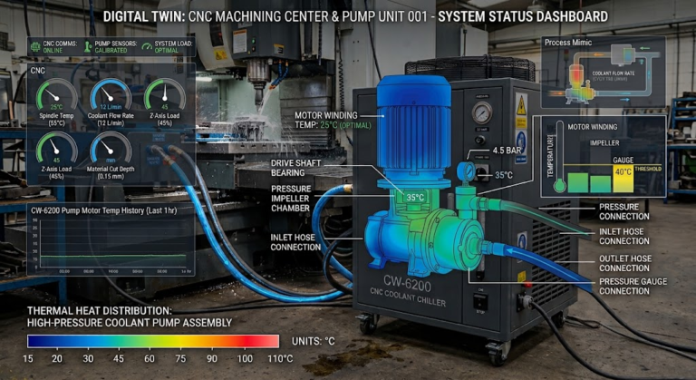
High-Volume CNC Milling: Complete Production Guide
High-Volume CNC Milling Defined: The Production Evaluation Framework
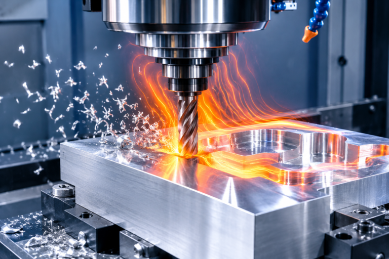
High-volume CNC milling transforms subtractive prototyping into a highly automated, cost-competitive mass production engine. When annual component demand moves from hundreds to tens of thousands of units, machining strategies pivot entirely from machine setup flexibility to cycle-time minimization, statistical process control, and minimal operator intervention.
High-volume CNC milling is defined as the industrialized, continuous production of tight-tolerance components (typically 5,000 to 500,000+ parts per annum) utilizing automated pallet systems, dedicated hydraulic tombstone fixturing, adaptive toolpath strategies, and closed-loop in-process metrology.
Executing scalable production runs requires a rigid engineering framework. Procurement and hardware engineering teams must evaluate production suppliers across four core operational pillars:
- Kinematic Efficiency: Maximizing cutting engagement via multi-spindle, multi-axis, or multi-pallet Horizontal Machining Centers (HMCs) to maintain spindle utilization rates exceeding 85%.
- Process Capability Index (Cp / CpK): Maintaining statistical dispersion thresholds where process capability metrics reach CpK ≥ 1.67, ensuring less than 1 defective part per million opportunities.
- Automated In-Line Verification: Integrating in-spindle optical triggers and laser tool setters to mitigate tool-wear drift and thermal dimensional variations in real time.
- Dedicated Workholding Architecture: Amortizing custom modular fixtures and hydraulic clamping systems to machine multiple parts per pallet cycle, minimizing chip-to-chip dead time.
Engineering teams utilizing precision CNC milling services leverage these evaluation parameters to transition mechanical architectures from pilot builds into repeatable, high-output production runs without dimensional degradation.
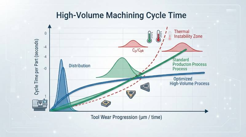
The Economics of High-Volume Milling: Unit Cost Drivers and Toolpath Optimization
Unit economics in high-volume CNC milling are driven by three factors: cycle time per unit, tool life longevity, and raw material utilization. Unlike low-volume job shop machining where setup time dominates final part costs, mass production unit costs reflect pure cycle-time efficiency.
Hydraulic Workholding Amortization
Manual vise clamping creates human-dependent load variations and extends downtime. High-volume runs justify custom hydraulic or pneumatic tombstone fixtures holding 8, 16, or 32 parts per setup. The capital expenditure of a 15,000 custom multi-station hydraulic fixture amortizes to just0.15 per unit across a 100,000-part production contract.
Dynamic Toolpath Strategies & Coolant Delivery
Trochoidal milling and adaptive clearing strategies maintain a constant radial chip load, preventing tool spike loads during corner engagements. Combined with 70-bar (1,000 PSI) High-Pressure Through-Spindle Coolant (TSC), cutting temperatures remain stable, chip evacuation is instantaneous, and tool life increases by up to 250%.
Vf = n × z × fz
Where: Vc = Cutting Speed (m/min), D = Tool Diameter (mm), n = Spindle Speed (RPM), Vf = Table Feed Rate (mm/min), z = Number of Flutes, fz = Feed per Tooth / Chip Load (mm/tooth)
Optimizing feed rates (Vf) based on exact tool substrate wear curves enables cutting speeds (Vc) exceeding 600 m/min in Al 6061-T6, cutting overall roughing cycle time by up to 45%.
Machining Automation & Cell Architecture: HMC vs VMC vs 5-Axis Lights-Out Cells
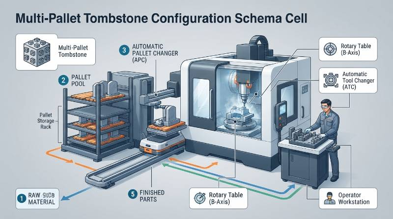
Selecting the machine platform dictates both production throughput and lights-out reliability. While 3-axis Vertical Machining Centers (VMCs) suit low-mix flat geometries, high-volume production relies on multi-pallet Horizontal Machining Centers (HMCs) and automated 5-axis robotic cells.
| Architecture Type | Primary Strengths | Chip Evacuation | Spindle Utilization | Optimal Annual Volume |
|---|---|---|---|---|
| 3-Axis VMC | Low capital cost, rapid single-part setups | Fair (Gravity causes recutting) | 45% – 60% | 500 – 2,500 units |
| Multi-Pallet HMC | Tombstone fixturing, multi-sided access, continuous pallet swapping | Superior (Gravity drops chips away) | 80% – 92% | 10,000 – 100,000+ units |
| 5-Axis Automated Cell | Single-setup complex parts, robotic part loading | Excellent (Rotational orientation) | 85% – 95% | 5,000 – 50,000+ units |
In HMC systems, gravity naturally clears chips out of deep cavities, preventing tool re-cutting—the leading cause of premature micro-chipping on carbide edges. Leveraging advanced multi-axis machining cells with zero-point robotic clamping eliminates human changeover idle time, running continuous 24/7 lights-out schedules.
Statistical Quality Assurance: Achieving CpK ≥ 1.67 in Continuous Runs
Maintaining micro-inch precision over tens of thousands of components demands real-time statistical process control (SPC) compliant with ISO 9001:2015 and automotive IATF 16949 standards. A machining process that drift-fails even 0.1% of features generates intolerable scrap costs at scale.
In-Process Closed-Loop Probing
Automated manufacturing cells integrate in-spindle optical probes (such as Renishaw OMP60). The machine measures critical datum points and bore diameters directly inside the fixture before un-clamping. If thermal expansion or tool wear creates a ±0.003 mm variance, the CNC controller automatically updates its wear compensation register for the subsequent cycle.
Automated Zeiss CMM Batch Inspection
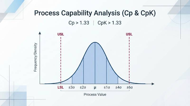
Parts pulled on strict lot frequencies undergo automated coordinate measuring machine (CMM) routines in climate-controlled metrology labs (20°C ± 0.5°C). Statistical analysis software continuously calculates process capability:
CpK = min[(USL – μ) / (3 × σ), (μ – LSL) / (3 × σ)]
Where: USL = Upper Specification Limit, LSL = Lower Specification Limit, μ = Process Mean, σ = Standard Deviation. Target: CpK ≥ 1.67.
Maintaining a CpK ≥ 1.67 guarantees that dimensional spread stays comfortably within the upper and lower engineering tolerance boundaries, keeping true position variance within ±0.005 mm across multi-shift operations.
Material Selection & Machinability Guidelines for Mass Milling
Material machinability directly affects cycle time, cutter wear rates, and total production cost. Choosing the correct structural alloy balances functional strength against cycle-time penalties. Browse our full engineering materials catalog for detailed mechanical property sheets.
| Material Grade | Machinability Index (%) | Recommended Cutting Speed (Vc) | Tool Substrate & Coating | Typical High-Volume Applications |
|---|---|---|---|---|
| Al 6061-T6 | 100% (Baseline) | 400 – 900 m/min | Uncoated / DLC Carbide | Electronic enclosures, heatsinks, automotive brackets |
| Al 7075-T6 | 80% | 300 – 700 m/min | DLC / ZrN Coated Carbide | Aerospace structural nodes, high-stress robotics |
| AISI 316L | 35% | 80 – 160 m/min | AlTiN / AlCrN Coated Solid Carbide | Medical device housings, fluid manifolds |
| 17-4 PH (H1150) | 45% | 100 – 190 m/min | TiSiN Multi-layer Carbide | Aerospace fasteners, high-wear actuator components |
| PEEK (Virgin / GF30) | 70% | 150 – 350 m/min | Polished Uncoated / Diamond PCD | Semiconductor wafer carriers, implantable housings |
For high-volume aluminum milling, Polycrystalline Diamond (PCD) inserts and Diamond-Like Carbon (DLC) tool coatings prevent aluminum built-up edge (BUE), allowing uninterrupted spindle operation for over 120 cutting hours per tool setup.
High-Volume CNC Milling vs Alternative Manufacturing Processes: Break-Even Analysis
A frequent dilemma for manufacturing engineers is deciding when to utilize pure CNC milling versus near-net-shape methods like High-Pressure Die Casting (HPDC), Metal Injection Molding (MIM), or stamping. Exploring our integrated stamping and casting solutions provides context for these hybrid paths.
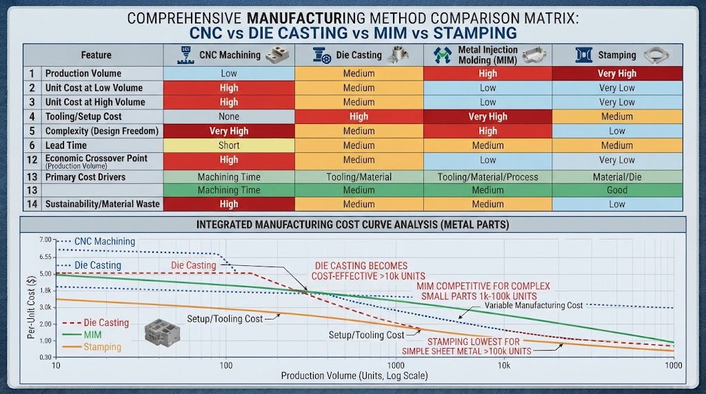
| Parameter | High-Volume CNC Milling | High-Pressure Die Casting (HPDC) | Metal Injection Molding (MIM) |
|---|---|---|---|
| Tooling / NRE Costs | Low (2,000 –8,000 for fixtures) | High (30,000 –100,000+ per steel mold) | High (15,000 –50,000 tooling) |
| Dimensional Tolerance | ±0.005 mm to ±0.02 mm | ±0.1 mm (requires post-machining) | ±0.3% to ±0.5% |
| Surface Roughness (Ra) | Ra 0.4 μm to Ra 0.8 μm | Ra 1.6 μm to Ra 3.2 μm | Ra 0.8 μm to Ra 1.6 μm |
| Design Flexibility | High (Immediate G-code updates) | Very Low (Steel tool rework needed) | Low (Hard mold modifications) |
| Cost Break-Even Point | 1 to 50,000 units (pure billet) | > 50,000 units (plus post-CNC ops) | > 25,000 miniature complex parts |
For components with frequent iteration cycles, high structural density needs (zero porosity), or tight mating surfaces, high-volume CNC milling remains the superior production path well past 50,000 units, bypassing long 12-week die fabrication lead times.
High-Precision Automotive & Electronics Chassis: The 50,000-Unit Benchmark
To demonstrate high-volume CNC precision, consider a recent production benchmark: mass producing 50,000 units per year of an Al 6061-T6 Automotive Electronic Control Unit (ECU) heat-sink chassis.
The Engineering Constraints
- True Position: 42 M3 threaded mounting holes held to a continuous true position of ⌀0.02 mm relative to primary datums.
- Surface Roughness: Continuous perimeter O-ring sealing groove requiring Ra 0.8 μm without post-polishing.
- Thin-Wall Deflection: Integrated heat-dissipation fin array with 0.8 mm wall thickness across an 80 mm pocket depth.
- Thread Verification: 100% thread integrity inspection with zero broken taps across 2.1 million total tapped holes.
Manufacturing Strategy and Results
The manufacturing architecture deployed two 4-axis Horizontal Machining Centers operating a 6-sided tombstone holding 24 chassis per cycle. Roll form tapping replaced standard cutting taps to eliminate chip packing and eliminate tap breakage. Thermal compensation probing executed every 4 pallet rotations.
The final capability analysis showed a CpK of 1.78 on hole positioning, with zero thread defects across the full 50,000-part production batch and a continuous cycle time of 2.1 minutes per finished enclosure.
The Tyneen 4-Pillar High-Volume Milling Protocol
Tyneen executes mass production orders through a deterministic manufacturing process designed to eliminate setup variation and spindle downtime:
- Predictive Thermal Drift Modeling: Spindle and ball-screw thermal sensors continuously compensate for ambient and friction expansion, keeping physical dimensional shift under 0.002 mm across continuous 24-hour operations.
- Adaptive High-Feed Toolpaths: CAM toolpaths dynamically adjust engagement angles and feed per tooth, maintaining consistent cutting force and extending tool life by up to 300%.
- Closed-Loop In-Spindle Metrology: In-process optical probing verifies critical reference planes and depths prior to final finishing passes, automatically adjusting tool offsets in real time.
- Automated CMM Batch Lot Sampling: Metrology inspection routines run statistical analysis on automated Zeiss CMMs, providing full digital inspection traceability with every shipment.
Tyneen Scalable Manufacturing Capabilities & Quality Verification
Operating an advanced fleet of DMG MORI, Makino, and Brother machining centers, Tyneen delivers scalable production for aerospace, automotive, medical, and industrial electronics sectors.
- Certified Quality Systems: Fully certified to ISO 9001:2015, IATF 16949 (Automotive), and AS9100D (Aerospace).
- Multi-Pallet HMC Capacity: 4-axis and 5-axis horizontal multi-pallet lines for uninterrupted lights-out production.
- Integrated Turned-Milled Components: High-speed Swiss-turn and multi-turret turning through our dedicated precision CNC turning services.
- Metrology & Traceability: Zeiss coordinate measuring machines (CMM), Keyence optical comparators, roughometers, and complete Mill Test Certificate (MTR) raw material traceability.
DFM Engineering Best Practices for High-Volume CNC Milling
Design for Manufacturability (DFM) directly governs unit production pricing. Implementing these geometric best practices in your CAD models reduces cycle times and tooling spend.
1. Optimize Internal Corner Radii (r/D ≥ 0.3)
Avoid sharp 90° internal vertical corners. Design the internal corner radius (r) to be at least 15% to 30% larger than the milling cutter radius (D/2). This prevents the tool from dwelling in corners, reducing chatter and tool breakage while allowing higher feed rates.
2. Maintain Pocket Depth-to-Width Ratios (≤ 4:1)
Cavities deeper than 4× tool diameter induce tool deflection and require slower peck cycles. Where deep cavities are unavoidable, incorporate a 1° to 2° draft angle on sidewalls to improve cutter clearance.
3. Standardize Thread Depths
Limit thread engagement depths to 1.5× to 2× the nominal thread diameter. Tapping deeper provides negligible tensile holding strength while dramatically increasing tap wear and breakage risks on mass production lines.
4. Design Self-Locating Datum Features
Incorporate consistent external locating tabs, tooling holes, or planar datum pads. This ensures instantaneous, error-proof mechanical alignment during automated robotic loading and multi-station clamping.
Frequently Asked Questions About High-Volume CNC Milling
How are tight tolerances held during continuous 24/7 spindle runs?
Tight tolerances down to ±0.005 mm are maintained through machine-chassis chilling units, dynamic spindle thermal expansion software offsets, periodic automated tool breakage detection cycles, and routine in-spindle probe re-zeroing.
What is the minimum order quantity (MOQ) for high-volume pricing?
Production economies of scale typically begin at 1,000 units. Full high-volume amortized pricing models—incorporating dedicated multi-part hydraulic tombstone fixturing—reach peak cost efficiency at runs of 5,000 to 100,000+ units per year.
How does Tyneen verify material composition and surface plating?
Every raw material billet is accompanied by a full Mill Test Certificate (MTR) verifying chemical composition and heat lot data. Surface finishes (such as Type II/III anodizing, electroless nickel, and passivating) undergo salt spray corrosion and coating thickness verification.
What quality documentation accompanies mass production orders?
We provide full First Article Inspection (FAI) reports per AS9102 standards, Automotive PPAP Level 3 documentation (including PFMEA, Control Plans, Gage R&R, and CpK studies), material certs, and Certificates of Conformance (CoC).
Accelerate Your High-Volume Production: 3-Step DFM and Scaling Pathway
Scale your mechanical hardware from engineering validation into high-rate production through Tyneen’s streamlined manufacturing pathway:
The 3-Step Production Scaling Pathway
Submit your 3D STEP/IGES files along with 2D drawings defining critical tolerances, surface finishes, and quality control specifications.
Our engineering team analyzes tool accessibility, cycle time drivers, and material optimization to deliver actionable DFM feedback alongside tiered volume pricing.
Approve rapid FAI production samples with full Zeiss CMM reports, followed by immediate ramp-up across our multi-pallet HMC production cells.