CNC Milling DFM Guide: Engineering for Cost Efficiency
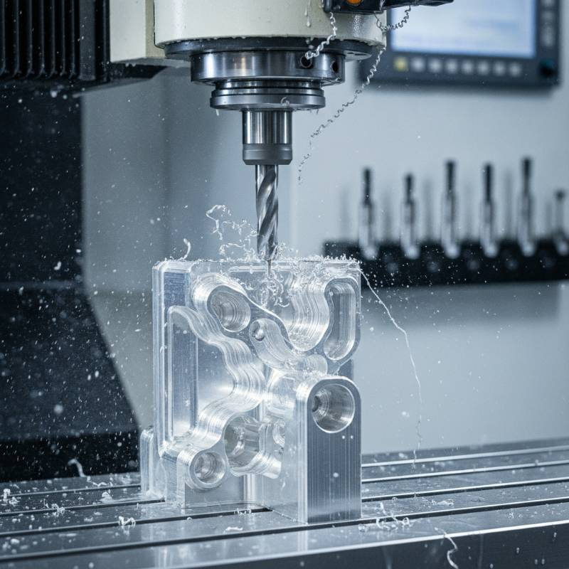
By integrating value engineering CNC principles early, you bridge the gap between a perfect CAD model and a cost-effective physical part. This guide breaks down the technical levers that reduce cycle times and maximize the value of CNC Machining Services.
What is DFM for CNC Milling?
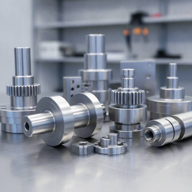
DFM for CNC milling is the strategic alignment of part geometry with the physical realities of subtractive manufacturing. It involves optimizing features to fit standard tooling, minimizing material waste, and ensuring the part can be held securely during high-speed operations.
Effective DFM prevents “unmanufacturable” flags in procurement and ensures that every minute of spindle time adds direct value to the end product. It is the core of Precision Engineering Solutions.
The Precision-Efficiency Matrix: Our Proprietary DFM Framework
At Tyneen, we utilize the Precision-Efficiency Matrix (PEM) to evaluate design viability. This framework balances three critical pillars: Geometric Complexity, Material Hardness, and Tolerance Requirements.
Instead of viewing these as isolated variables, the PEM identifies the “sweet spot” where performance meets profitability. For example, a complex geometry in a soft material like Aluminum 6061 might be more cost-effective than a simple geometry in Inconel 718. Understanding this interplay allows our engineers to suggest modifications that maintain functional integrity while slashing overhead.
“Over-tolerancing is the silent killer of project budgets. If a +/- 0.005″ tolerance works, specifying +/- 0.001″ can triple the cost for zero functional gain. DFM is about finding the widest possible tolerance that still ensures perfect function.”
— Senior Manufacturing Engineer, Tyneen
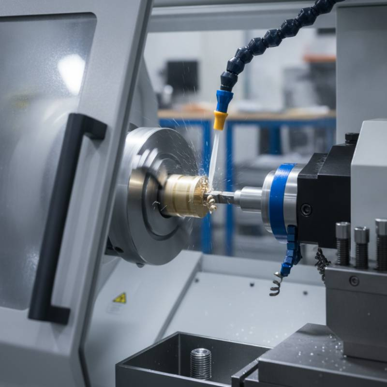
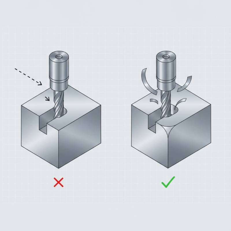
Geometry Optimization: Solving the Internal Corner Dilemma
One of the most frequent cost-drivers in CNC milling is the request for sharp internal corners. Because CNC milling uses rotating cylindrical end mills, a perfectly square internal corner is physically impossible to achieve without expensive secondary processes like EDM (Electrical Discharge Machining).
The 10% Rule for Corner Radii
To optimize for speed, design internal corners with a radius slightly larger than the radius of the cutting tool. If you plan to use a 0.5″ end mill, specify a corner radius of 0.275″ (0.25″ + 10%).
This prevents the tool from “burying” into the corner, which causes vibration (chatter), tool deflection, and potential breakage. Uniform radii across the entire part also allow the machine to maintain a constant feed rate, significantly reducing tool path optimization bottlenecks.
Depth-to-Diameter Ratios: Data-Driven Cost Reduction
Deep cavities require long tools, which are inherently less rigid. As the length-to-diameter ratio of a tool increases, it becomes more susceptible to deflection.
| Depth-to-Diameter Ratio | Machining Difficulty | Estimated Cost Impact |
|---|---|---|
| Under 3:1 | Standard / Optimal | Baseline |
| 3:1 to 5:1 | Moderate | +15% to 20% |
| Over 5:1 | Extreme / High Risk | +50% or more |
Our data shows that reducing a pocket’s depth-to-diameter ratio from 5:1 to 3:1 can save up to 20% in total machining time. This is due to the ability to use higher feed rates and larger depths of cut without risking surface finish degradation.
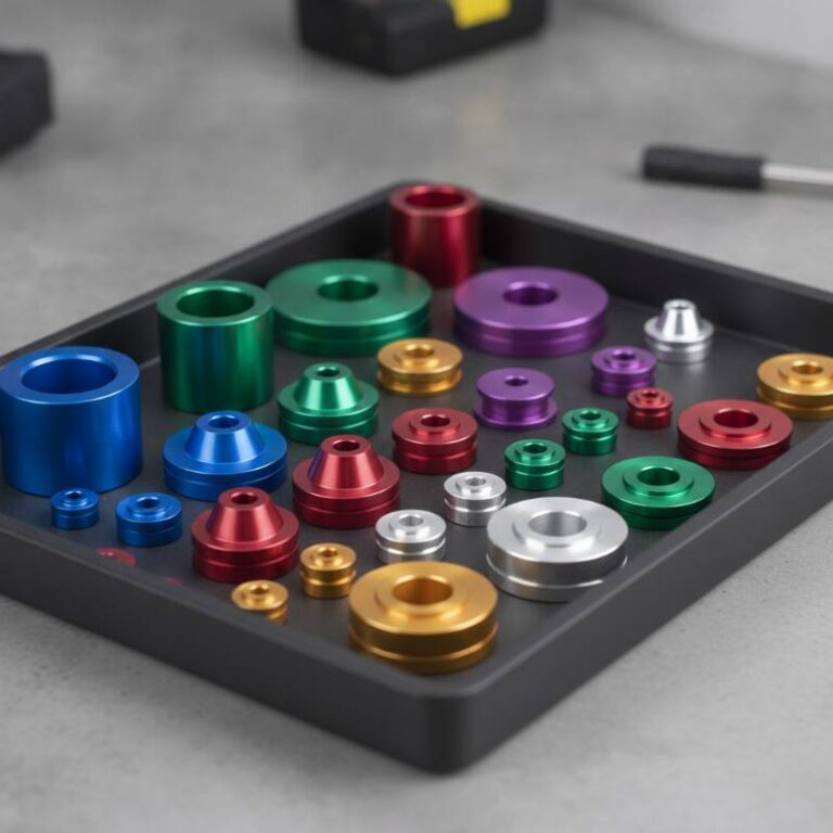
Material Selection and ASME Y14.5 GD&T Standards
Choosing the right material is the first step in CNC cost optimization. We recommend consulting our Material Selection Guide to match mechanical properties with machinability ratings.
Applying ASME Y14.5
To prevent over-engineering, we strictly adhere to ASME Y14.5 Geometric Dimensioning and Tolerancing (GD&T) standards. GD&T allows designers to specify the function of a part rather than just its dimensions. By using “positional” tolerances instead of standard +/- coordinate tolerances, you can provide the machine shop with more “bonus tolerance,” which reduces scrap rates and lowers cost.
Definition: ASME Y14.5 is an international standard that establishes uniform practices for stating and interpreting GD&T and related requirements for use on engineering drawings.
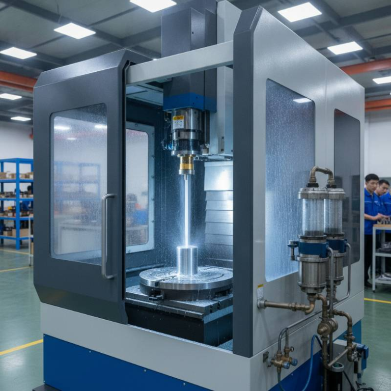
Operational Efficiency: Minimizing Setups and Workholding
Every time a machinist has to stop the machine, unclamp a part, and flip it to a new orientation, the cost increases. Setups involve manual labor and introduce the risk of “stacking” errors between different orientations.
By designing parts that can be machined from as few directions as possible (ideally one or two), you minimize setup reduction time. If a part requires 5-axis machining, ensure the geometry allows for standard workholding access to avoid custom fixture costs. In our testing, reducing a part from three setups to two directly lowered total unit costs by 15%.

Advanced Frontiers: Green Milling and AI-Generative Design
As we move through 2026, Green Milling—the practice of optimizing toolpaths to reduce energy consumption and coolant waste—is becoming a standard requirement for sustainable supply chains. AI-generative design tools are now capable of flagging unmanufacturable features in real-time, allowing engineers to fix issues before they ever reach the shop floor.
These AI systems analyze material machinability and surface finish requirements to suggest the most efficient cycle time analysis. This proactive approach ensures that your Precision Engineering Solutions are future-proofed against rising energy and material costs.
2026 CNC Machining Cost-Reduction Checklist
Before submitting your drawings for quote, use this self-check to ensure your design is optimized for 2026 manufacturing standards:
- Are all internal corner radii at least 10% larger than a standard end mill size?
- Have you limited pocket depths to a 3:1 ratio where possible?
- Can the part be machined in 2 or fewer setups?
- Have you applied ASME Y14.5 GD&T to avoid tight tolerances on non-critical features?
- Are your wall thicknesses at least 0.5mm (for metals) to prevent warping?
Ready to optimize? Upload your drawings for a free engineering cost assessment from our elite technical team.
Frequently Asked Questions About CNC DFM
What is the minimum wall thickness for CNC milling?
For most aluminum alloys, a minimum wall thickness of 0.5mm is recommended. For plastics, 1.0mm is safer to prevent melting or deformation during the milling process.
How does surface roughness impact cost?
Standard “as-machined” finishes (3.2 μm Ra) are the most cost-effective. Requiring a 0.8 μm Ra or better often requires slower feeds and specialized tooling, increasing costs by 20-30%.
Can DFM help with thread depths?
Yes. Tapping deep holes is risky and slow. A thread depth of 1.5 to 2 times the diameter is usually sufficient for maximum strength. Anything deeper adds cost without adding significant holding power.
Scale Your Production with Tyneen
Join the leading aerospace and medical firms utilizing our AI-ready DFM frameworks to reduce costs by up to 35%.